


Rain Alarm
#rain alarm
#555 timer
#astable multivibrator
#water sensor
#alarm circuit
#sensor
#security
#weather detection
#electronic alarm
#moisture detection
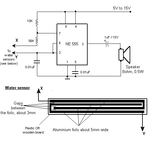
Description: Rain Alarm. This circuit activates an alarm when its sensor comes into contact with water. It utilizes a 555 astable multivibrator.
The rain alarm circuit operates on the principle of detecting moisture through a sensor that can be designed using two conductive plates or probes. When water bridges the gap between these plates, it changes the resistance and allows current to flow, triggering the alarm mechanism. The heart of this circuit is the 555 timer configured in astable mode, which continuously oscillates between high and low states.
In this configuration, the 555 timer's output can be connected to a speaker or an LED to indicate the presence of water. The frequency of oscillation is determined by the resistors and capacitors connected to the 555 timer, allowing for customization of the alarm tone or visual indication.
To build the circuit, the following components are typically required:
- A 555 timer IC
- Two conductive probes for the moisture sensor
- Resistors (typically in the range of kilo-ohms)
- A capacitor (usually in the microfarad range)
- A speaker or LED for the alarm output
- A power supply (typically a battery or DC power source)
The probes should be placed in a location where they can effectively detect rainwater. The resistors and capacitor values can be adjusted to set the desired sensitivity and response time of the alarm. When the sensor is activated, the 555 timer switches its output state, activating the alarm and alerting users to the presence of moisture.
Overall, this rain alarm circuit provides a simple yet effective solution for detecting rainfall, making it useful for various applications, including irrigation systems, automated greenhouses, and home safety systems.Rain Alarm. This circuit gives out an alarm when its sensor is wetted by water. A 555 astable multivibrator is used.
The rain alarm circuit operates on the principle of detecting moisture through a sensor that can be designed using two conductive plates or probes. When water bridges the gap between these plates, it changes the resistance and allows current to flow, triggering the alarm mechanism. The heart of this circuit is the 555 timer configured in astable mode, which continuously oscillates between high and low states.
In this configuration, the 555 timer's output can be connected to a speaker or an LED to indicate the presence of water. The frequency of oscillation is determined by the resistors and capacitors connected to the 555 timer, allowing for customization of the alarm tone or visual indication.
To build the circuit, the following components are typically required:
- A 555 timer IC
- Two conductive probes for the moisture sensor
- Resistors (typically in the range of kilo-ohms)
- A capacitor (usually in the microfarad range)
- A speaker or LED for the alarm output
- A power supply (typically a battery or DC power source)
The probes should be placed in a location where they can effectively detect rainwater. The resistors and capacitor values can be adjusted to set the desired sensitivity and response time of the alarm. When the sensor is activated, the 555 timer switches its output state, activating the alarm and alerting users to the presence of moisture.
Overall, this rain alarm circuit provides a simple yet effective solution for detecting rainfall, making it useful for various applications, including irrigation systems, automated greenhouses, and home safety systems.Rain Alarm. This circuit gives out an alarm when its sensor is wetted by water. A 555 astable multivibrator is used.

555 circuits
The Switchgate is a simple dual gate circuit based on a 556 timer configured in monostable mode, featuring a trigger input that activates two switches. The outputs of the monostables are also available individually. Recent research has led to the...
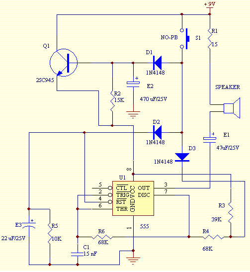
Door Bell Chime Project
Construct a doorbell chime using a 555 timer integrated circuit, a speaker, five resistors, four electrolytic capacitors, one ceramic capacitor, three diodes, a pushbutton switch, and a 9V battery as the power supply.
The circuit design for the doorbell chime utilizes...

Diesel and Horn Circuit for Train
This circuit is a module for a diesel and horn train system. It is constructed using a 555 timer IC and several operational amplifiers (op-amps). The circuit serves as a complete system for the horn function. The main power supply...
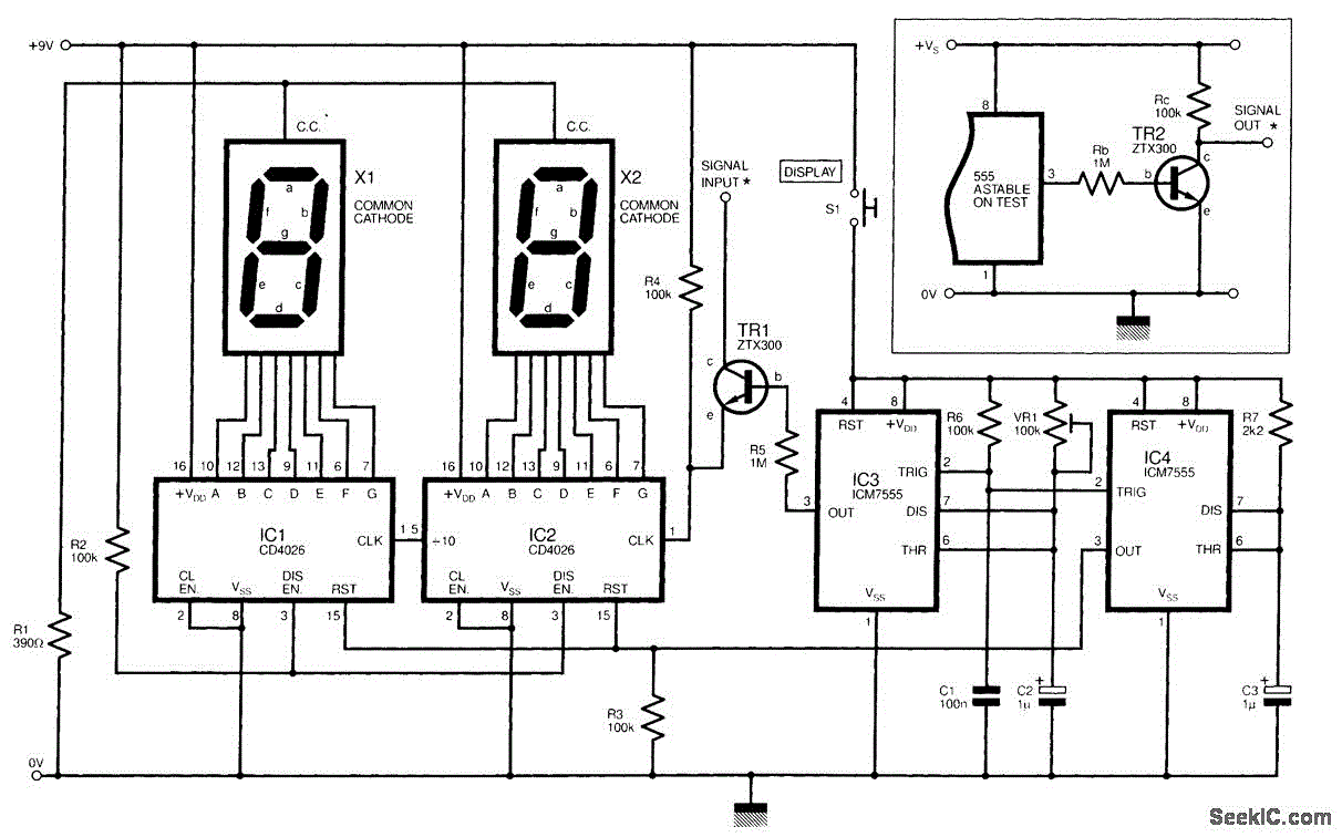
555 ASTABLE_FREQUENCY METER
The circuit illustrated is a straightforward digital frequency meter that displays the frequency in hertz of an astable 555 timer. It may potentially be modified for alternative applications. An NPN transistor, TR2, is linked to the 555 astable timer being...
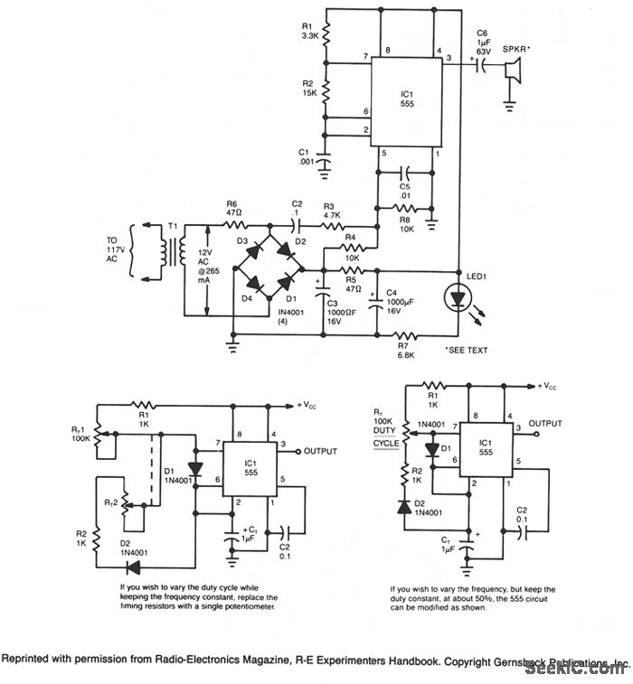
ULTRASONIC PEST REPELLER
This circuit utilizes a 555 timer integrated circuit (IC) configured as a square-wave generator. The base frequency is approximately 45 kHz, determined by the resistor values R1, R2, and the capacitor C1. The 45 kHz carrier frequency is modulated by...
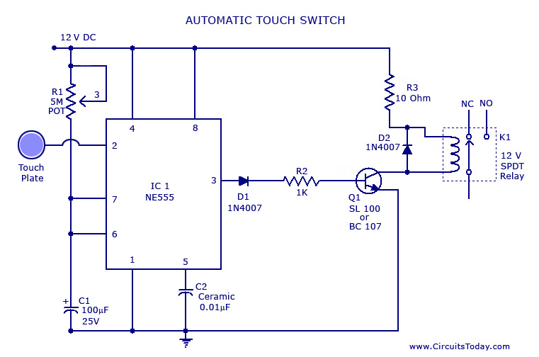
Touch SwitchCircuit using NE 555 IC
A touch switch circuit schematic utilizing a 555 integrated circuit (IC). When the touch plate is activated, a relay is switched ON for a predetermined duration, which can also be adjusted.
The touch switch circuit employs a 555 timer IC configured...
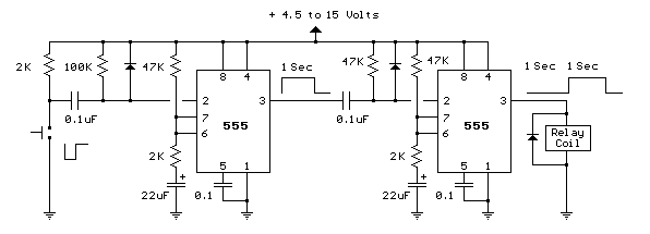
Delaying Pulse from 555 circuit
The circuit below illustrates generating a single positive pulse which is delayed relative to the trigger input time. The circuit is similar to the one above but employs two stages so that both the pulse width and delay can be...
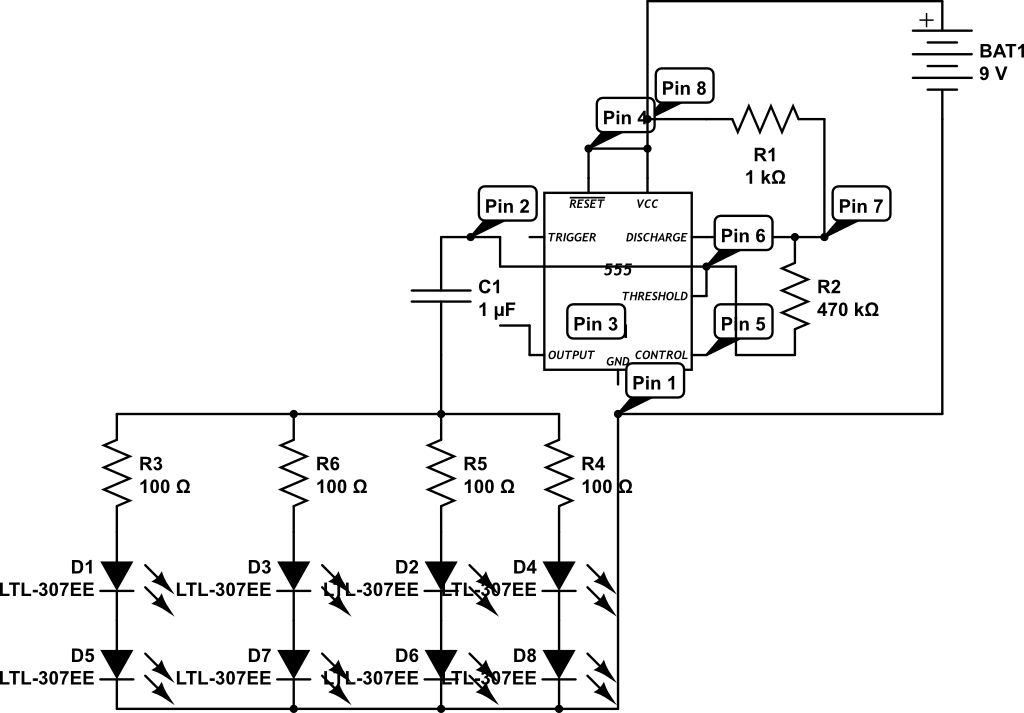
555 circuit for 8 leds flashing
LEDs are rated for a continuous current of only 30 mA, while this circuit operates them at approximately 50 mA. Although this is acceptable for low duty cycles with short pulses, the intended design has a high duty cycle. This...
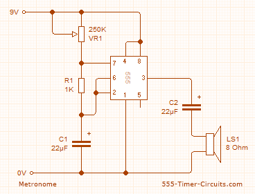
metronome
This circuit employs the 555 timer configured in astable mode to produce a continuous square wave output from Pin 3. The output is subsequently filtered through a 22.5 µF electrolytic capacitor to generate a smooth oscillation, resulting in a 'toc-toc'...