


Rain alarm-door bell
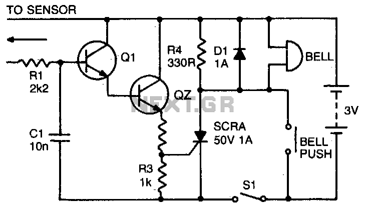
Description: When the switch SI is open, the circuit operates as a doorbell. When SI is closed, rain falling on the sensor will activate transistor Q1, which in turn triggers Q2 and the thyristor, thereby activating the bell. Resistor R4 provides holding current for the thyristor, while diode D1 protects the thyristor from back EMF generated by the bell coil. The sensor can be constructed from a 3 square inch piece of copper-clad board with a razor cut down the center. Additionally, capacitor Cl prevents any mains interference in the sensor leads.
The circuit described functions primarily as a rain-activated doorbell system. The operation begins with the switch SI, which controls the overall functionality of the circuit. When SI is in the open state, the circuit remains inactive, allowing it to function as a standard doorbell. In contrast, closing SI initiates the rain detection mechanism, which is crucial for the circuit's primary operation.
The rain sensor, crafted from a copper-clad board, utilizes a physical cut to create two conductive paths. When rainwater bridges this cut, it completes the circuit and activates transistor Q1. This transistor serves as a signal amplifier, enhancing the current flow to transistor Q2. The activation of Q2 subsequently triggers the thyristor, which is responsible for controlling the bell's operation.
Resistor R4 plays a vital role in maintaining the thyristor's conduction state once it is activated. This holding current ensures that the thyristor remains in the "on" state, allowing the bell to ring continuously until the circuit is interrupted. Diode D1 is strategically placed to protect the thyristor from potential damage caused by back electromotive force (back EMF) generated when the bell coil is de-energized. This protection is critical in preventing circuit failure and extending the operational lifespan of the components.
The addition of capacitor Cl enhances the circuit's reliability by filtering out any mains interference that could affect the sensor's performance. By preventing mains pickup in the sensor leads, Cl ensures that the rain detection mechanism operates without false triggers, thereby improving the overall accuracy and functionality of the doorbell system.
Overall, this circuit design exemplifies a practical application of basic electronic components to create a functional and reliable rain-activated doorbell system.With SI open the circuit functions as a doorbell. With SI closed, rain falling on the sensor will turn on Ql, triggering Q2 and the thyristor and activating the bell, R4 provides the holding for the thyristor while Dl prevents any damage to the thyristor from back EMF in the bell coil. The sensor can be made from 3 square inches of copper clad board with a razor cut down the center Cl prevents any mains pickup in the sensor leads.
The circuit described functions primarily as a rain-activated doorbell system. The operation begins with the switch SI, which controls the overall functionality of the circuit. When SI is in the open state, the circuit remains inactive, allowing it to function as a standard doorbell. In contrast, closing SI initiates the rain detection mechanism, which is crucial for the circuit's primary operation.
The rain sensor, crafted from a copper-clad board, utilizes a physical cut to create two conductive paths. When rainwater bridges this cut, it completes the circuit and activates transistor Q1. This transistor serves as a signal amplifier, enhancing the current flow to transistor Q2. The activation of Q2 subsequently triggers the thyristor, which is responsible for controlling the bell's operation.
Resistor R4 plays a vital role in maintaining the thyristor's conduction state once it is activated. This holding current ensures that the thyristor remains in the "on" state, allowing the bell to ring continuously until the circuit is interrupted. Diode D1 is strategically placed to protect the thyristor from potential damage caused by back electromotive force (back EMF) generated when the bell coil is de-energized. This protection is critical in preventing circuit failure and extending the operational lifespan of the components.
The addition of capacitor Cl enhances the circuit's reliability by filtering out any mains interference that could affect the sensor's performance. By preventing mains pickup in the sensor leads, Cl ensures that the rain detection mechanism operates without false triggers, thereby improving the overall accuracy and functionality of the doorbell system.
Overall, this circuit design exemplifies a practical application of basic electronic components to create a functional and reliable rain-activated doorbell system.With SI open the circuit functions as a doorbell. With SI closed, rain falling on the sensor will turn on Ql, triggering Q2 and the thyristor and activating the bell, R4 provides the holding for the thyristor while Dl prevents any damage to the thyristor from back EMF in the bell coil. The sensor can be made from 3 square inches of copper clad board with a razor cut down the center Cl prevents any mains pickup in the sensor leads.
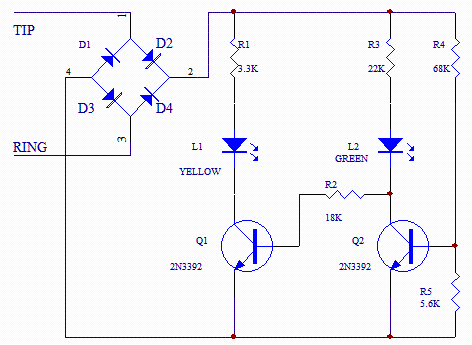
Phone In Use Electronics Project
Phone In Use Indicator Electronics Project using 5 resistors, 2 NPN transistors, 4 diodes, and 2 light-emitting diodes.
The Phone In Use Indicator is an electronic project designed to visually indicate when a telephone line is active. This circuit employs a...
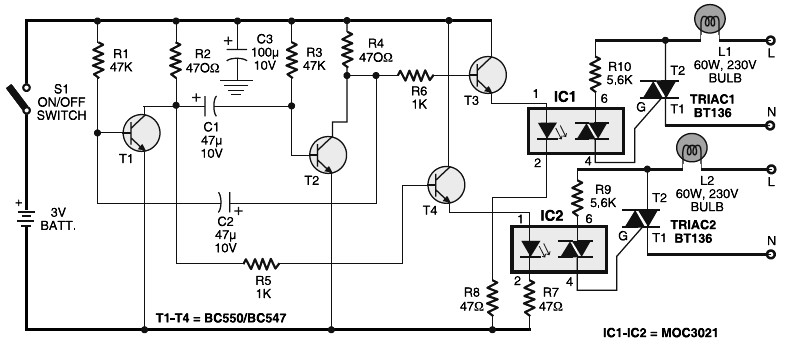
Portable 230V lamp flasher circuit diagram
Portable 230V lamp flasher circuit diagram. The circuit is entirely transistorized and powered by a battery. A free-running oscillator circuit is implemented using two low-power, low-noise transistors, T1 and T2. One of these transistors remains in a conducting state while...
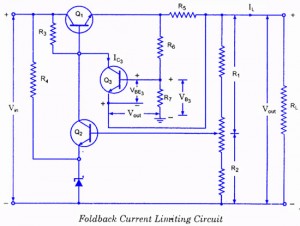
Controlled Transistor Series Regulator With Overload and Short-Circuit Protection
If the load resistance (RL) is reduced or the load terminals are accidentally shorted, a very large load current will flow, potentially damaging the pass transistor (Q1), diode, or other components. Fuse protection may not be sufficient, as the transistor...
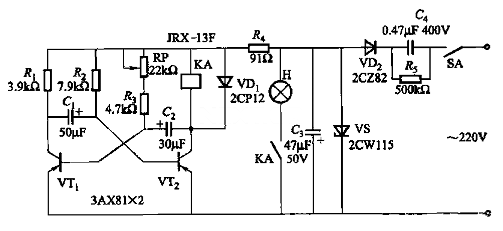
Seven blinker circuits
The circuit features a self-excited multivibrator composed of transistors VTi and VTZ. It includes an adjustment potentiometer RP and two RC networks that influence the transistors' parameters, specifically the timing for light activation and deactivation.
The described multivibrator circuit utilizes two...
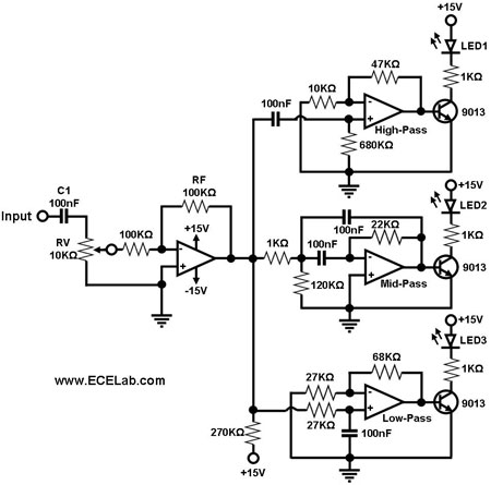
Sound To Dancing Lights Converter With 9013 Transistor
The simple circuit for converting an audio signal. The circuit basically consists of a buffer/amplifier stage and three filter circuits.
The audio signal conversion circuit is designed to process audio signals efficiently while maintaining signal integrity. The circuit architecture includes a...
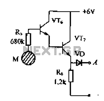
Delay electronic doorbell circuit - touch doorbell amplifier circuit
Delay electronic doorbell circuit - touch doorbell amplifier circuit
The delay electronic doorbell circuit is designed to provide a user-friendly interface for doorbell activation, utilizing a touch-sensitive amplifier circuit. This circuit typically incorporates a touch sensor that detects user interaction, triggering...
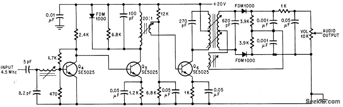
SOUND I F FOR COLOR TV
Utilizes three transistor stages and a Foster-Seeley discriminator to produce an audio output of 1 V peak-to-peak. -D. Bray, Solid State Makes Debut in Big Screen Color TV, Electronics, 39:8, p 99-105.
The circuit in question employs a combination of three...
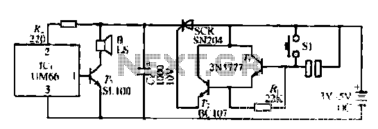
Musical doorbell circuit with two trigger modes
A few custom integrated circuits began to play music. When the song ends, no electricity flows through the thyristor, which then cuts off the light, causing the phototransistor to activate. The system is designed with a touchpad; each touch generates...

Transistor Pulse Generator
Seven narrow pulses ranging from 2 Hz to 50 kHz are generated by this circuit. Capacitors C1 through C4 provide frequency ranges in decode steps. Resistors R1 and R2 regulate the charging time of capacitors C1 through C4. R2 is...