


scr high power alarm driver circuit design
#SCR
#high power
#alarm driver
#trigger circuit
#security system
#electronic switch
#low power SCR
#high power SCR
#circuit design
#sensor trigger
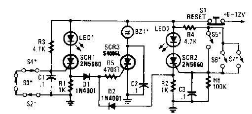
Description: A straightforward high-power alarm driver electronic project can be developed using this circuit diagram. This high-power alarm driver project utilizes a low-power SCR to trigger a high-power SCR. When switches S2, S3, or S4 are opened or switches S5, S6, or S7 are closed, either SCR1 or SCR2 is activated. This, in turn, triggers SCR3 through diodes D1, D2, and resistor R5. When the alarm is active, the BZ1 buzzer will sound continuously until the S1 reset switch is pressed. This electronic circuit requires only a few components and must be powered by a DC power supply that provides an output voltage between 6 and 12 volts.
The circuit operates on the principle of semiconductor switching using silicon-controlled rectifiers (SCRs). The initial activation of SCR1 or SCR2 occurs through the manipulation of the designated switches. When S2, S3, or S4 is opened, SCR1 is triggered, while closing S5, S6, or S7 activates SCR2. Both SCRs serve as gate control devices that, once triggered, remain in a conductive state until the power is interrupted or reset.
Diodes D1 and D2 play a crucial role in the circuit by ensuring that the current flows in the correct direction to trigger SCR3. Resistor R5 is used to limit the current flowing through the triggering path, protecting the SCRs from excessive current that could damage them.
The buzzer (BZ1) is an essential component of the alarm system, providing an audible alert when the circuit is activated. The continuous sound of the buzzer serves as a warning signal until the reset switch (S1) is engaged, allowing the user to deactivate the alarm and reset the system.
Power supply considerations are important for the functionality of this circuit. A DC power supply capable of delivering a voltage between 6 and 12 volts is required to ensure proper operation of the SCRs and the buzzer. The choice of power supply voltage may affect the performance of the circuit, particularly the volume of the buzzer.
This alarm driver circuit is suitable for various applications where a high-power alarm is necessary, providing a reliable and effective solution with minimal component requirements.A very simple high power alarm driver electronic project can be designed using this circuit diagram. This high power alarm driver electronic project is based on low power SCR which trigger a high power SCR. When a switch is opening (S2, S3, S4) or closing (S5, S6, S7), either SCR1 or SCR2 triggers. This triggers SCR3 via D1, D2, and R5. When t he alarm is active the BZ1 buzzer will sound continuously, until the S1 reset switch is preset. This electronic circuit require few electronic components and must be powered from a dc power supply circuit, that will provide an output voltage between 6 and 12 volt.
The circuit operates on the principle of semiconductor switching using silicon-controlled rectifiers (SCRs). The initial activation of SCR1 or SCR2 occurs through the manipulation of the designated switches. When S2, S3, or S4 is opened, SCR1 is triggered, while closing S5, S6, or S7 activates SCR2. Both SCRs serve as gate control devices that, once triggered, remain in a conductive state until the power is interrupted or reset.
Diodes D1 and D2 play a crucial role in the circuit by ensuring that the current flows in the correct direction to trigger SCR3. Resistor R5 is used to limit the current flowing through the triggering path, protecting the SCRs from excessive current that could damage them.
The buzzer (BZ1) is an essential component of the alarm system, providing an audible alert when the circuit is activated. The continuous sound of the buzzer serves as a warning signal until the reset switch (S1) is engaged, allowing the user to deactivate the alarm and reset the system.
Power supply considerations are important for the functionality of this circuit. A DC power supply capable of delivering a voltage between 6 and 12 volts is required to ensure proper operation of the SCRs and the buzzer. The choice of power supply voltage may affect the performance of the circuit, particularly the volume of the buzzer.
This alarm driver circuit is suitable for various applications where a high-power alarm is necessary, providing a reliable and effective solution with minimal component requirements.A very simple high power alarm driver electronic project can be designed using this circuit diagram. This high power alarm driver electronic project is based on low power SCR which trigger a high power SCR. When a switch is opening (S2, S3, S4) or closing (S5, S6, S7), either SCR1 or SCR2 triggers. This triggers SCR3 via D1, D2, and R5. When t he alarm is active the BZ1 buzzer will sound continuously, until the S1 reset switch is preset. This electronic circuit require few electronic components and must be powered from a dc power supply circuit, that will provide an output voltage between 6 and 12 volt.
Who-is-first
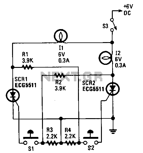
This control circuit utilizes two silicon-controlled rectifiers (SCRs) to ensure that only one lamp is illuminated at any given time. The first lamp (I1) is activated by SCR1, which is triggered when switch S1 is pressed. Similarly, the second lamp...
power supply for 1500 watt audio power amplifier
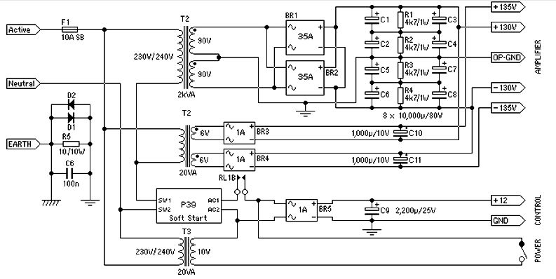
Power supply for a 1500-watt audio power amplifier. This power supply circuit is paired with a high-power audio amplifier rated at 1500 watts. A serious approach is required to design the power supply for the amplifier. First, a step-down transformer...
high power regulator
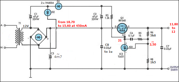
The half-linear design allows for reduced thermal considerations, as the linear regulator only needs to handle 1-5W instead of the full 75W per rail. MOSFETs operate in their linear region, just below the rated voltage for RDS(on), but they are...
SCR_LATCH
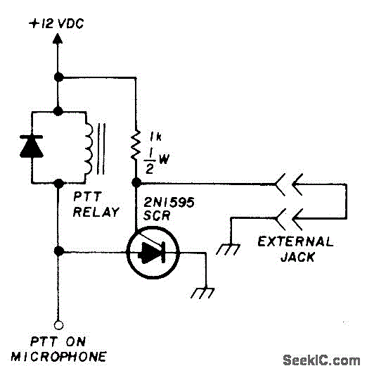
Activates a mobile transceiver or other mobile equipment when power is applied, especially if the external circuit is interrupted during theft. The transmitter will then emit an unmodulated carrier signal even if the Push-To-Talk (PTT) switch is disconnected or turned...
High power control for sensitive contacts
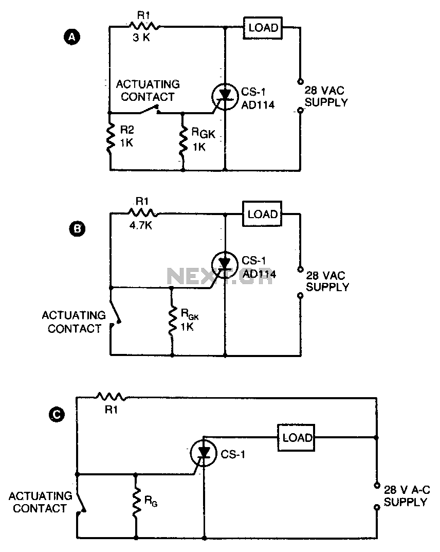
Two simple arrangements for resistive loads are shown in A and B. The circuit in A will provide load power when the actuating contact is closed, and no power when the contact is open. B provides the reverse of this...
Scr-flasher
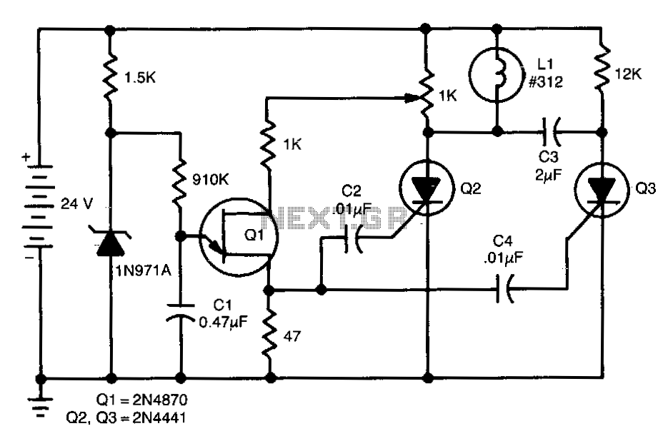
This de-flasher utilizes two SCRs and a unijunction oscillator clock to establish the flash rate, which can be adjusted by modifying the value of C1.
The circuit described operates as a de-flasher, a device commonly used in lighting applications to...
High-voltage-ac-switcher
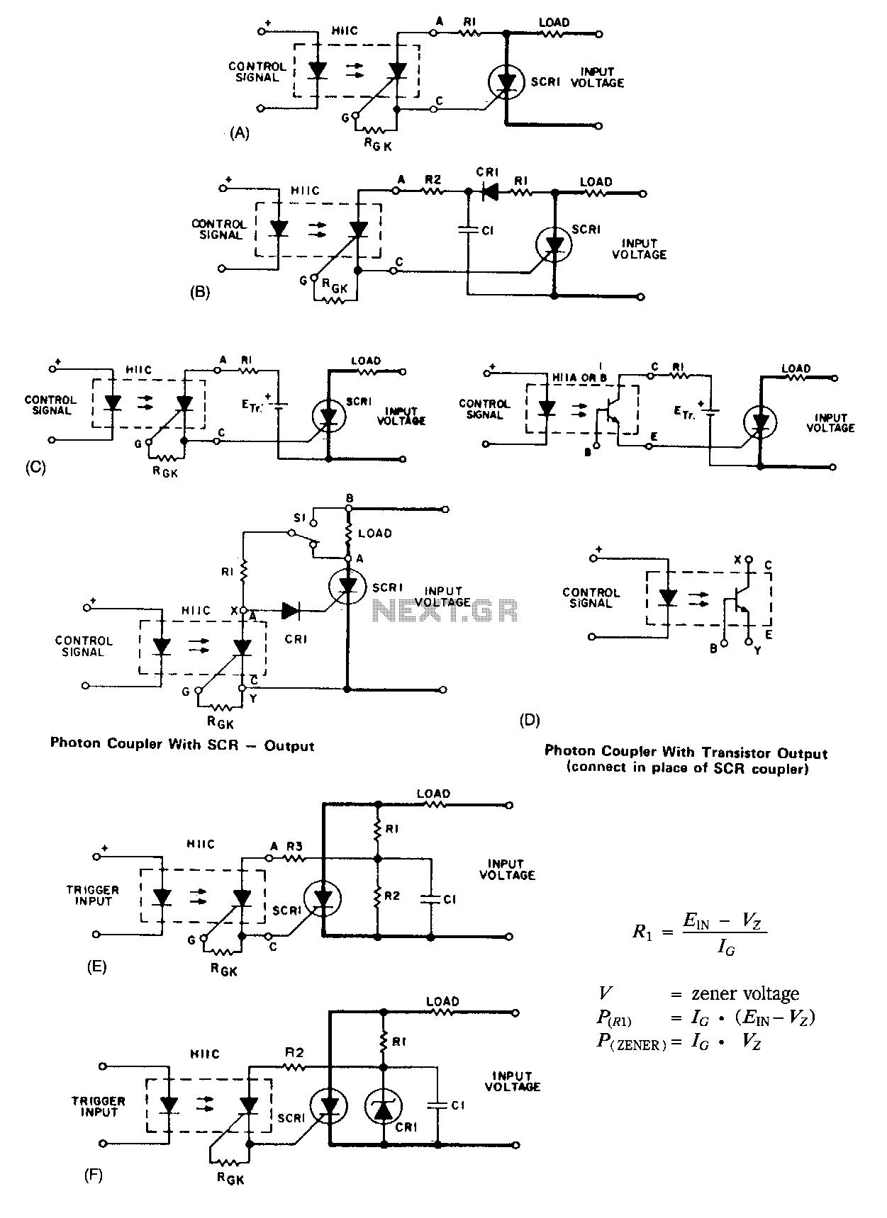
A basic circuit to trigger a silicon-controlled rectifier (SCR) is illustrated in Figure 67-1A. This circuit has the limitation that the blocking voltage of the photonic coupler output device dictates the circuit's blocking voltage, despite the SCR's higher voltage capability....
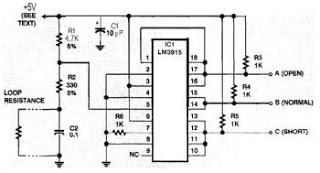
safe and security system
This security system is essential for homes, offices, and factories. It includes a circuit diagram that is simple and easy to construct, making it accessible for anyone. The circuit is cost-effective. Many security systems utilize a closed loop of wires...
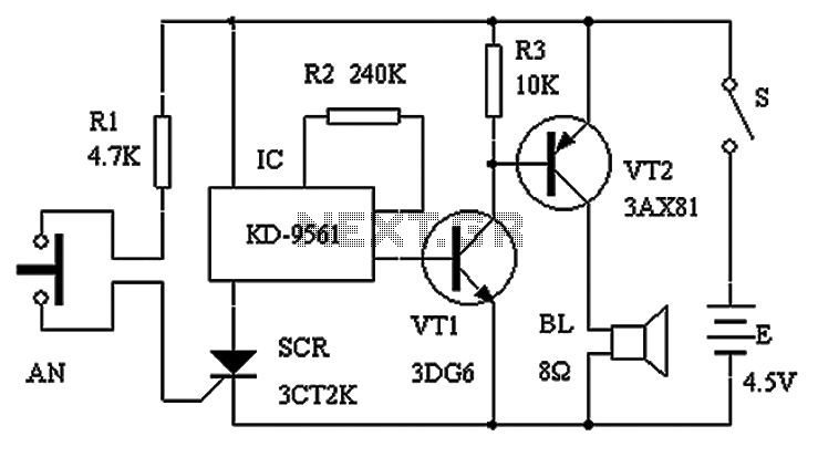
Normally closed contact burglar alarm circuit diagram
The circuit schematic presented in Figure 1 consists of an SCR, R1, and an AN SCR trigger switch circuit, along with an analog circuit composed of IC1, R2, VT1, VT2, and a BL siren. Typically, the circuit is designed to...