


SOS Alarm centralized control circuit
#SOS alarm
#centralized control
#anti-theft
#hospital bed call
#multi-storey buildings
#dormitories
#warehouses
#three-channel

Description: The SOS Alarm centralized control circuit is designed for use in calling a hospital bed and can also serve as an anti-theft alarm in multi-storey buildings, dormitories, warehouses, and similar locations. The circuit, as depicted in Figure 13-64, features three monitoring channels, which can be expanded to accommodate additional connections. The circuit utilizes thyristor control and incorporates either the KD9 561 or CW9561 analog sound alarm integrated circuit (IC). A light-emitting diode (LED) is employed for position display, allowing for control of alarms from various locations.
The SOS Alarm centralized control circuit operates by integrating multiple monitoring positions to ensure comprehensive coverage and rapid response. Each monitoring channel can be connected to various input devices, such as push buttons or sensors, which activate the alarm system when triggered. The use of thyristors in the circuit allows for effective control of the alarm signals, enabling reliable operation under different conditions.
The KD9 561 or CW9561 analog sound alarm IC serves as the core component for generating audible alerts. These ICs are designed to produce a distinct sound when an alarm condition is met, ensuring that the alarm is noticeable even in noisy environments. The incorporation of a light-emitting diode (LED) provides a visual indication of the alarm status, with different colors or blinking patterns potentially representing various conditions or locations.
This circuit can be particularly beneficial in environments where immediate communication is crucial, such as healthcare facilities or security-sensitive areas. The flexibility of the design allows for customization based on specific requirements, including the number of monitoring positions and the type of alarm signals used. Overall, the SOS Alarm centralized control circuit represents a versatile solution for enhancing safety and security in various settings.SOS Alarm centralized control circuit can be used to call a hospital bed, can also be used in multi-storey buildings, dormitories, warehouses and other places of anti-theft alarm. The circuit shown in Figure l3-64. The circuit shown in three-channel monitoring position, can actually be a lot of road. Circuit thyristor control, KD9 561 or CW9561 analog sound alarm IC A light emitting diode for position display. It may be in a different position control alarm.
The SOS Alarm centralized control circuit operates by integrating multiple monitoring positions to ensure comprehensive coverage and rapid response. Each monitoring channel can be connected to various input devices, such as push buttons or sensors, which activate the alarm system when triggered. The use of thyristors in the circuit allows for effective control of the alarm signals, enabling reliable operation under different conditions.
The KD9 561 or CW9561 analog sound alarm IC serves as the core component for generating audible alerts. These ICs are designed to produce a distinct sound when an alarm condition is met, ensuring that the alarm is noticeable even in noisy environments. The incorporation of a light-emitting diode (LED) provides a visual indication of the alarm status, with different colors or blinking patterns potentially representing various conditions or locations.
This circuit can be particularly beneficial in environments where immediate communication is crucial, such as healthcare facilities or security-sensitive areas. The flexibility of the design allows for customization based on specific requirements, including the number of monitoring positions and the type of alarm signals used. Overall, the SOS Alarm centralized control circuit represents a versatile solution for enhancing safety and security in various settings.SOS Alarm centralized control circuit can be used to call a hospital bed, can also be used in multi-storey buildings, dormitories, warehouses and other places of anti-theft alarm. The circuit shown in Figure l3-64. The circuit shown in three-channel monitoring position, can actually be a lot of road. Circuit thyristor control, KD9 561 or CW9561 analog sound alarm IC A light emitting diode for position display. It may be in a different position control alarm.
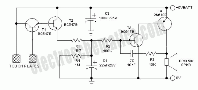
Bicycle Anti-Theft Alarm Project
The specific application of a bicycle is suggested due to its potential use in protecting various items from theft. This anti-theft alarm project is built around...
This anti-theft alarm system is designed to provide security for bicycles and similar items by...
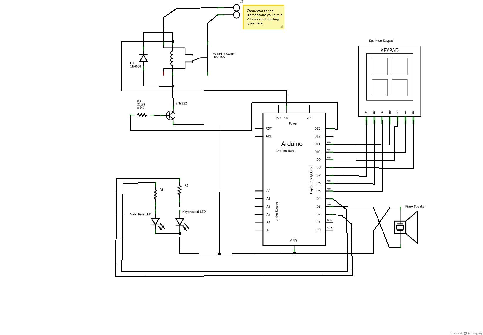
Car Anti-Theft System
Audible signals will alert if the password or keycode entered is accepted or not (in this case, random sounds for incorrect entries and the Super Mario theme for success) using a standard piezo speaker. The under-dashboard USB hub is ideal...
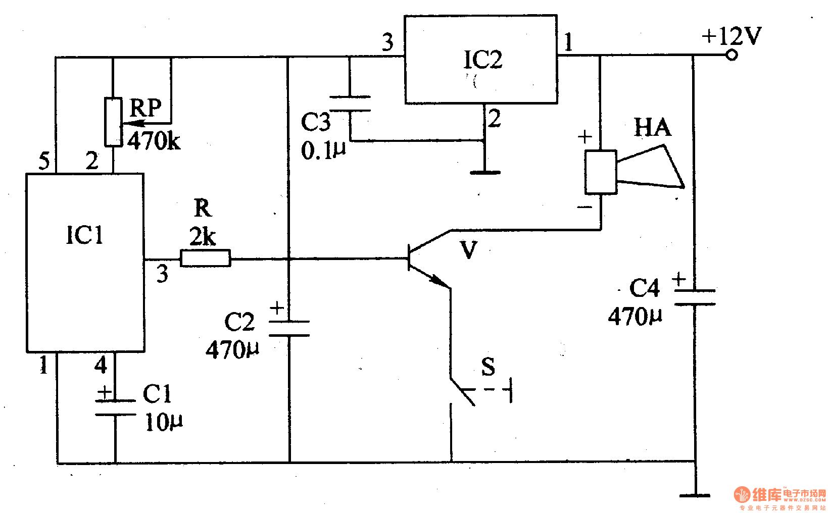
The motorcycle anti-theft alarm (4)
The motorcycle anti-theft alarm described in this article utilizes a proprietary displacement sensor. It is characterized by high sensitivity, good reliability, a low false alarm rate, and ease of construction. The principle of the circuit involves an integrated vibration displacement...
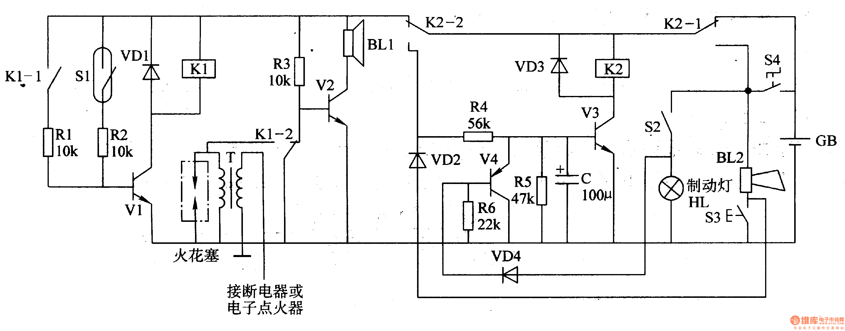
Anti-theft Alarm Of Motorcycle One
The circuit comprises a trigger circuit, an alarm control circuit, and a reset circuit for the alarm. The trigger circuit includes mercury switches (S1), a resistor, transistors (V1), and a relay (K1). The alarm control circuit is made up of...

Zero consumption Anti-theft High power Code Switch for E-Bike Batteries
This project is designed for a custom-made battery casing that provides ample space for concealing components. The switch can be adapted for various projects but is specifically tailored to meet e-bike requirements. It utilizes a clever thyristor functionality to create...
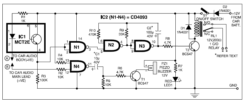
anti theft security for car audios
When 12V DC from the car battery is applied to the device (as indicated by LED1) through switch S1, the circuit enters standby mode. The LED inside the optocoupler IC1 illuminates as its cathode terminal is grounded via the car...
The motorcycle anti-theft alarm (4)
The motorcycle anti-theft alarm described in this article utilizes a proprietary displacement sensor. It is characterized by high sensitivity, good reliability, a low false alarm rate, and ease of construction. The principle of the circuit involves an integrated vibration displacement...
Anti-theft Alarm Of Motorcycle One
The circuit comprises a trigger circuit, an alarm control circuit, and a reset circuit for the alarm. The trigger circuit includes mercury switches (S1), a resistor, transistors (V1), and a relay (K1). The alarm control circuit is made up of...

Motorcycle anti-theft lock electronic circuit
The circuit operates using an ASIC lock IC, specifically the 5C058. Pins 1 to 6 are connected outside the key switch to the positive power supply, representing six valid key inputs. To unlock, keys A through F must be pressed...