


Sound-activated-tape-switch
#sound-activated
#op-amp
#comparator
#audio amplifier
#voltage doubler
#burglar alarm
#cassette recorder
#microphone
#sensor
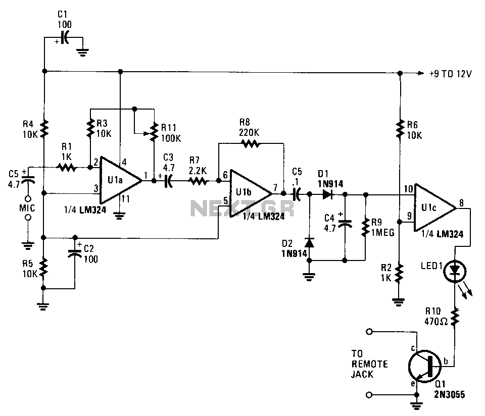
Description: This circuit can cause a cassette recorder to automatically turn on and record when a sound or noise is present. Another use is when the sound-activated switch is used to turn on a cassette player, allowing it to function as a burglar alarm detector and sounder. Operational amplifiers U1a and U1b are connected in tandem to amplify the sounds picked up by the detector's microphone. The amplified audio voltage, output at pin 7 of U1b, is fed to a voltage doubler circuit consisting of D1 and D2. The elevated voltage from the doubler circuit is input to the positive input of operational amplifier U1c, which operates as a simple comparator circuit. The other input of U1c is connected to a voltage divider that sets the switching point for the DC signal voltage, triggering the circuit when the signal level exceeds approximately 1.5 V. When the comparator activates, its output at pin 8 becomes positive and supplies a forward bias to turn on D3 and Q1, which in turn starts the recorder. The RC combination of C4 and R9 determines the cassette's run time after the input sound has ceased, preventing the recorder from stopping or cutting off between closely spaced sounds or words detected by the microphone. The delay time is approximately 6 to 8 seconds. Resistor R11 sets the circuit's gain. A low-impedance cassette microphone should be connected to the amplifier's input, and the output of Q1 should be connected to the cassette's remote input or to the internal input, with the recorder set to the record position. The amplifier's gain can be adjusted with R11 for the desired sensitivity.
This circuit is designed to provide automatic activation of a cassette recorder in response to ambient sound levels, making it suitable for applications such as security systems. The dual operational amplifier configuration ensures effective sound amplification, allowing for reliable detection of noise. The voltage doubler circuit enhances the output voltage, ensuring that the comparator receives a sufficient signal to trigger the recording function.
The comparator, configured with a voltage divider, establishes a threshold that determines when the circuit activates. This setting is crucial for filtering out background noise and ensuring that only significant sounds, such as speech or alarms, will trigger the recorder. The inclusion of a delay mechanism through the RC time constant formed by C4 and R9 prevents premature stopping of the recording, allowing for a seamless capture of sounds that occur in quick succession.
Additionally, the gain adjustment feature provided by R11 allows for fine-tuning of the circuit's sensitivity, accommodating various environments and sound levels. The recommended use of a low-impedance microphone ensures optimal performance, as it minimizes signal loss and maximizes the clarity of the captured audio. The connection of the output from Q1 to the cassette's input enables direct control of the recording process, streamlining the operation of the device.
Overall, this circuit represents a practical solution for sound-activated recording, with versatile applications in both personal and security-related audio capture scenarios.This circuit can cause a cassette recorder to automatically tum on and record when a sound or noise is present. Another use, is when the sound-activated switch is used to tum on a cassette player so that it operates as a burglar-alarm detector and sounder.
Op amps Ula and Ulb are connected in tandem to amplify the sounds picked up by the detector"s mike. The amplified audio voltage, output at pin 7 of Ulb, is fed to a voltage"doubler circuit, consisting of Dl and D2. The elevated voltage from the doubler circuit is input to the positive input of op amp Ulc, which is operating as a simple comparator circuit.
The other input of Ulc is connected to a voltage divider that sets the switching point for the de signal voltage, to turn on when the signal level is greater than about 1.5 V. As the comparator switches on, its output at pin 8 becomes positive and supplies a forward bias to tum on D3 and Ql, which in tum, starts the recorder.
The rc combination of C4/R9 sets the cassette"s run time after the input sound has ceased, preventing the recorder from chopping-up or turning-off between closely spaced sounds or words picked up by the mike. The delay time is roughly 6 to 8 seconds. Rll sets the circuit"s gain. Connect a low-impedance cassette mike to the amplifier"s input, and connect the output of Ql to the cassette"s remote input or to the internal input and set the recorder to the record position.
Talk and adjust the amplifier"s gain with Rll for the desired sensitivity.
This circuit is designed to provide automatic activation of a cassette recorder in response to ambient sound levels, making it suitable for applications such as security systems. The dual operational amplifier configuration ensures effective sound amplification, allowing for reliable detection of noise. The voltage doubler circuit enhances the output voltage, ensuring that the comparator receives a sufficient signal to trigger the recording function.
The comparator, configured with a voltage divider, establishes a threshold that determines when the circuit activates. This setting is crucial for filtering out background noise and ensuring that only significant sounds, such as speech or alarms, will trigger the recorder. The inclusion of a delay mechanism through the RC time constant formed by C4 and R9 prevents premature stopping of the recording, allowing for a seamless capture of sounds that occur in quick succession.
Additionally, the gain adjustment feature provided by R11 allows for fine-tuning of the circuit's sensitivity, accommodating various environments and sound levels. The recommended use of a low-impedance microphone ensures optimal performance, as it minimizes signal loss and maximizes the clarity of the captured audio. The connection of the output from Q1 to the cassette's input enables direct control of the recording process, streamlining the operation of the device.
Overall, this circuit represents a practical solution for sound-activated recording, with versatile applications in both personal and security-related audio capture scenarios.This circuit can cause a cassette recorder to automatically tum on and record when a sound or noise is present. Another use, is when the sound-activated switch is used to tum on a cassette player so that it operates as a burglar-alarm detector and sounder.
Op amps Ula and Ulb are connected in tandem to amplify the sounds picked up by the detector"s mike. The amplified audio voltage, output at pin 7 of Ulb, is fed to a voltage"doubler circuit, consisting of Dl and D2. The elevated voltage from the doubler circuit is input to the positive input of op amp Ulc, which is operating as a simple comparator circuit.
The other input of Ulc is connected to a voltage divider that sets the switching point for the de signal voltage, to turn on when the signal level is greater than about 1.5 V. As the comparator switches on, its output at pin 8 becomes positive and supplies a forward bias to tum on D3 and Ql, which in tum, starts the recorder.
The rc combination of C4/R9 sets the cassette"s run time after the input sound has ceased, preventing the recorder from chopping-up or turning-off between closely spaced sounds or words picked up by the mike. The delay time is roughly 6 to 8 seconds. Rll sets the circuit"s gain. Connect a low-impedance cassette mike to the amplifier"s input, and connect the output of Ql to the cassette"s remote input or to the internal input and set the recorder to the record position.
Talk and adjust the amplifier"s gain with Rll for the desired sensitivity.
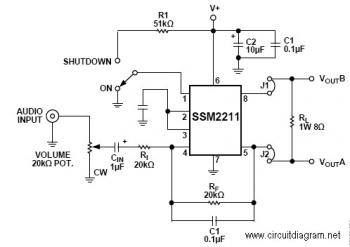
1.5W Audio Amplifier with IC SSM2211
The SSM22111 is a high-performance audio amplifier that delivers 1 W RMS of low distortion audio power into a bridge-connected 8-ohm speaker load (or 1.5 W RMS into a 4-ohm load). The SSM2211 operates over a wide temperature range and...
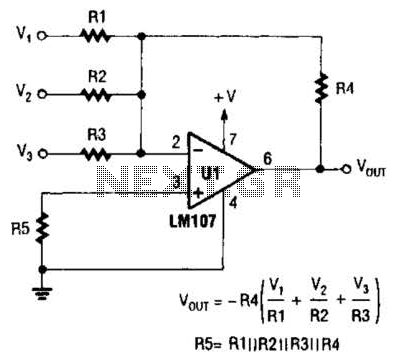
Inverting Summing Amplifier Circuit
The output of Ul is the sum of Vv, multiplied by the ratio of Rx to Rv, RJRV, and respectively. Resistors R1, R2, and R3 are selected as required for individual gains. Additionally, R4 influences the gain of all these...
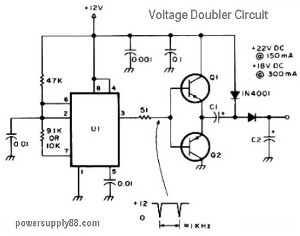
12V voltage doubler circuit
The schematic diagram originates from a 12V DC voltage doubler circuit power supply. This circuit diagram illustrates a DC voltage doubler/DC converter that transforms a 12V DC power supply into 24V DC and 18V DC outputs. It is compatible with...

2 Watt Mini Audio Amplifier
This circuit is inexpensive, easy to assemble, and quite straightforward. It is a general audio amplifier that can be used with computers, CD players, or other devices that have a headphone output. The circuit was intentionally designed without the use...
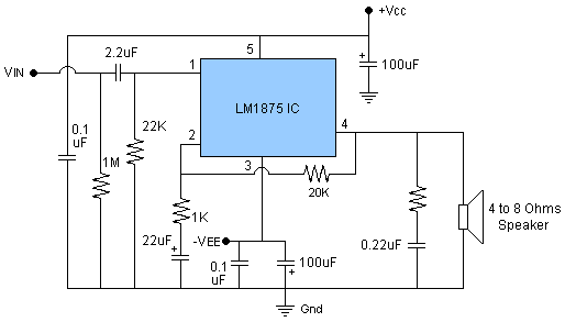
20w audio amplifier using lm1875
The circuit presented is a 20W audio amplifier utilizing the LM1875 integrated circuit (IC). The LM1875 is a high-quality, low-distortion audio amplifier IC rated for 20 watts, available in a TO-220 package. This IC includes several built-in features such as...
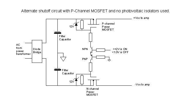
A DC Fault Protection Circuit for Audio Amplifiers
The standard Class AB audio power amplifier allows for direct coupling of the amplifier's output to speakers. This is beneficial as it eliminates capacitors or transformers that could compromise sound quality. The speakers are connected directly to the amplifying devices....
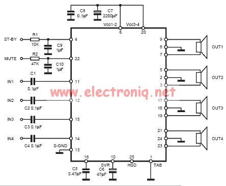
tda7384 class ab audio power amplifier circuit design electronic project
The input capacitor is used for low-frequency cut-off, with a standard value of 0.1 µF, resulting in a cut-off frequency of approximately 16 Hz.
The input capacitor plays a crucial role in filtering unwanted low-frequency signals in electronic circuits. By selecting...
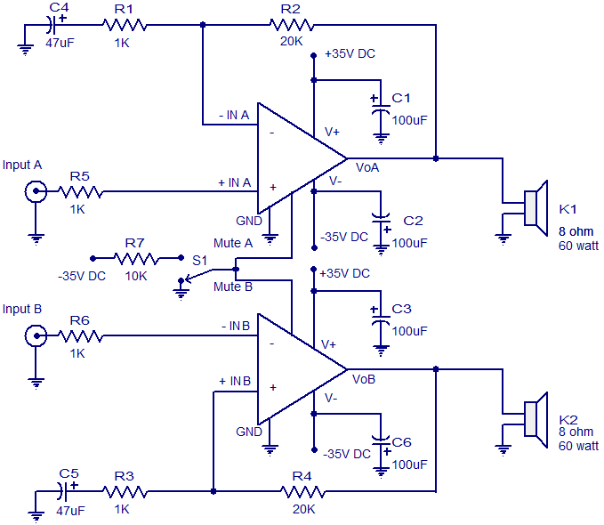
2 x 60 W audio amplifier circuit
The circuit diagram presented is for a 2 x 60 Watt stereo amplifier utilizing the LM4780 from National Semiconductors. The LM4780 is an excellent audio amplifier integrated circuit capable of delivering 60W RMS power output per channel into 8-ohm speakers....
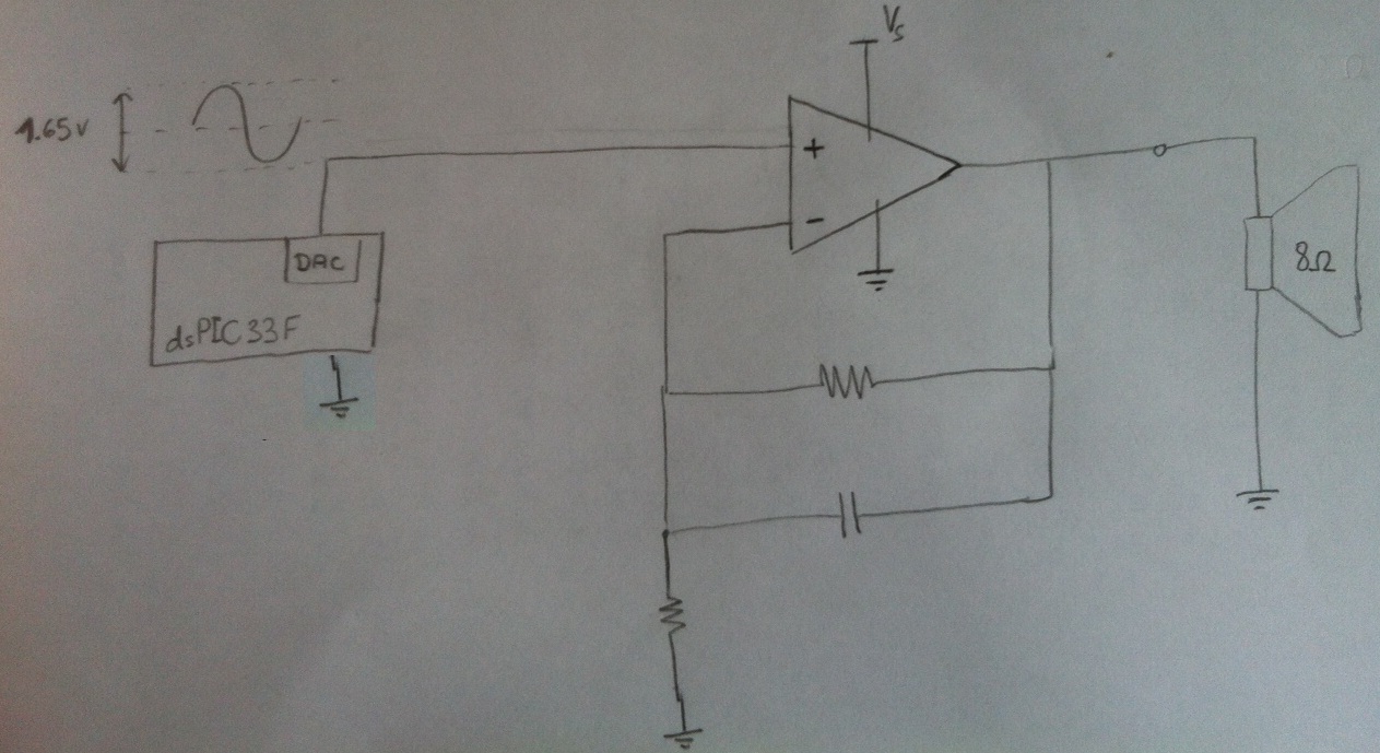
Audio Amplifier Op amp
Design a circuit in which a microcontroller produces a signal and then uses an amplifier to drive an 8-ohm speaker. The LM386 has been used previously, but it cannot exceed 1W, which is insufficient. Additionally, a second-order anti-aliasing low-pass filter...