


Strobe Alarm

Description: This strobe provides a visual indication of a sensor input. The input signal causes the light-dependent resistor (LDR) to change the charge across capacitors C1 and C3 through resistor R4. When NE1 fires, capacitor C3 discharges into SCR1, triggering it and causing capacitor C2 to discharge through trigger transformer T1, which activates Flashlamp FL1. The 330-V supply should have an output capacitance of approximately 50 to 100 µF. Inductor L1 provides about 25 mH of inductance to prolong the flash duration and the lifespan of FL1.
The described circuit is a strobe light system that visually indicates sensor input activity. The light-dependent resistor (LDR) serves as the primary sensor element, responding to changes in light levels. When the input signal is detected, the LDR alters its resistance, influencing the charging dynamics of capacitors C1 and C3. Resistor R4 plays a crucial role in this circuit by controlling the charge time of these capacitors, ensuring that the system responds appropriately to input signals.
Upon activation of the input signal, the circuit initiates a sequence where the neon bulb (NE1) fires, indicating that the voltage across it has reached a threshold. This firing event leads to the rapid discharge of capacitor C3 into the silicon-controlled rectifier (SCR1). The SCR acts as a switch that allows current to flow once it is triggered, thus energizing the circuit and allowing capacitor C2 to discharge through the trigger transformer (T1).
The role of the trigger transformer is significant; it steps up the voltage to a level sufficient to ignite the Flashlamp (FL1). The flashlamp then emits a bright flash of light, providing the visual indication intended by the circuit design. To ensure reliable operation, the power supply for this circuit is specified to provide a high voltage of 330 V, accompanied by a capacitance of 50 to 100 µF. This output capacitance is essential for stabilizing the voltage and ensuring that the flashlamp receives sufficient energy for operation.
Inductor L1, with its 25 mH inductance, is integrated into the circuit to manage the energy discharge rate. This inductance helps to prolong the flash duration, enhancing the visual effect while also contributing to the overall longevity of the flashlamp. The design considerations surrounding component values, such as the capacitance and inductance, are critical for achieving the desired performance characteristics of the strobe system, ensuring that it functions reliably in response to sensor inputs. This strobe gives a visual indication of a sensor input. The input signal causes Ul, a light dependent resistor, to chaijge CI and C3 through R4. When NE1 fires, C3 discharges into SCR1, which triggers it and causes C2 to discharge through trigger transformer Tl, which triggers Flashlamp FL1, The 330-V supply should have about 50 to 100 /iF output capacitance. Ll supplies about 25-mH inductance to prolong the flash and the life of FL1.
The described circuit is a strobe light system that visually indicates sensor input activity. The light-dependent resistor (LDR) serves as the primary sensor element, responding to changes in light levels. When the input signal is detected, the LDR alters its resistance, influencing the charging dynamics of capacitors C1 and C3. Resistor R4 plays a crucial role in this circuit by controlling the charge time of these capacitors, ensuring that the system responds appropriately to input signals.
Upon activation of the input signal, the circuit initiates a sequence where the neon bulb (NE1) fires, indicating that the voltage across it has reached a threshold. This firing event leads to the rapid discharge of capacitor C3 into the silicon-controlled rectifier (SCR1). The SCR acts as a switch that allows current to flow once it is triggered, thus energizing the circuit and allowing capacitor C2 to discharge through the trigger transformer (T1).
The role of the trigger transformer is significant; it steps up the voltage to a level sufficient to ignite the Flashlamp (FL1). The flashlamp then emits a bright flash of light, providing the visual indication intended by the circuit design. To ensure reliable operation, the power supply for this circuit is specified to provide a high voltage of 330 V, accompanied by a capacitance of 50 to 100 µF. This output capacitance is essential for stabilizing the voltage and ensuring that the flashlamp receives sufficient energy for operation.
Inductor L1, with its 25 mH inductance, is integrated into the circuit to manage the energy discharge rate. This inductance helps to prolong the flash duration, enhancing the visual effect while also contributing to the overall longevity of the flashlamp. The design considerations surrounding component values, such as the capacitance and inductance, are critical for achieving the desired performance characteristics of the strobe system, ensuring that it functions reliably in response to sensor inputs. This strobe gives a visual indication of a sensor input. The input signal causes Ul, a light dependent resistor, to chaijge CI and C3 through R4. When NE1 fires, C3 discharges into SCR1, which triggers it and causes C2 to discharge through trigger transformer Tl, which triggers Flashlamp FL1, The 330-V supply should have about 50 to 100 /iF output capacitance. Ll supplies about 25-mH inductance to prolong the flash and the life of FL1.
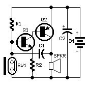
Personal Alarm
This circuit, enclosed in a small plastic box, can be placed into a bag or handbag. A small magnet is placed close to the reed switch and connected to the hand or the clothes of the person carrying the bag...
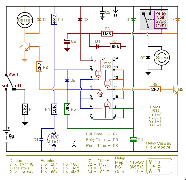
An Enhanced Shed / Garage Alarm circuit
This is an improved version of the basic Garage/Shed Alarm. The Entry and Exit delays have been extended to approximately 30 seconds, and a timed Siren cut-off along with an automatic reset feature has been added. Additionally, the LED has...
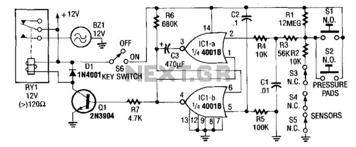
Automatic Turn-Off Alarm With Delay
In this circuit, IC1A and IC1B serve as a monostable multivibrator. Any input from the sensors SI through S5 triggers IC1A to produce a logic low signal, which activates IC1B, turning on Q1 until the capacitor C3 discharges through resistor...
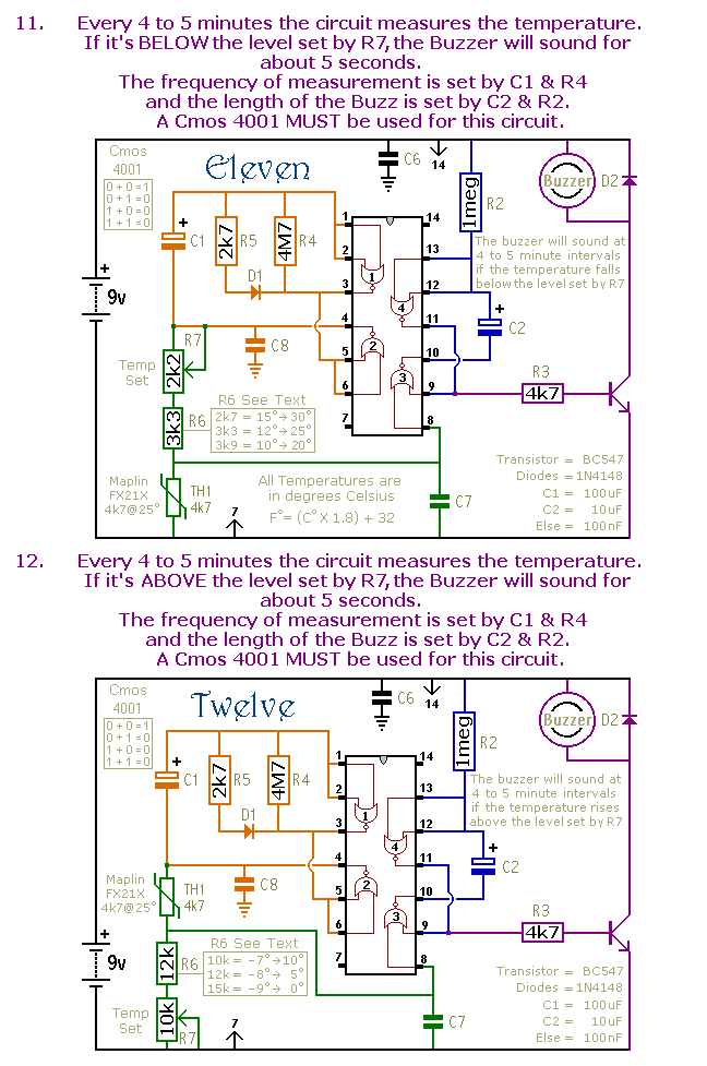
Mini Alarms
This is a selection of small self-contained alarm circuits. They have a very low standby current; and are suitable for battery operation.
The described alarm circuits are compact and designed for low power consumption, making them ideal for battery-powered applications. These...

Security alarm
This alarm features both open-loop and closed-loop detection systems along with an automatic alarm shutoff mechanism. It provides a 15-second delay for exit and entrance. Additionally, the alarm activation time can be adjusted from 1 to 15 minutes.
The alarm system...
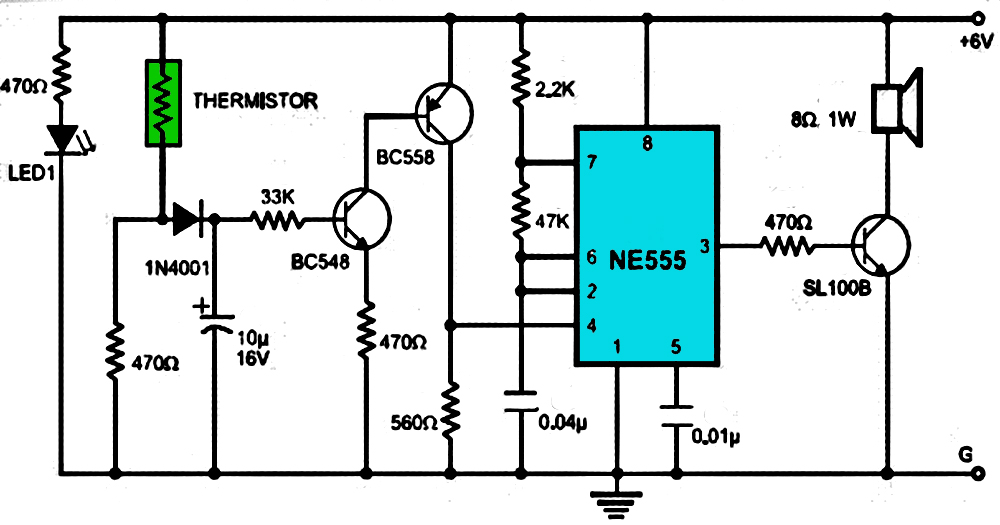
Alarm
This is a simple and easy-to-build multi-tone alarm circuit that can be utilized in burglar alarms or sirens. The circuit is based on the dual op-amp MC1458 and LM380. The two op-amps within the MC1458 are configured to generate square...

Key Code Combination High Security Door Lock
This project involves an electronic lock that supports numerous combinations, which can be easily modified. It unlocks only with the correct sequence of four consecutive numbers. A significant feature of this electronic lock is that the four numbers must be...
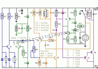
Single Alarm Circuit
This is a single alarm circuit. The circuit includes automatic exit and entry delays, a timed bell cut-off, and a system reset. It has provisions for normally open and normally closed inputs.
The single alarm circuit is designed to provide security...
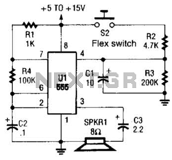
Alarm Sounder For Flex Switch Circuit
This is a cross-sectional diagram of a flex switch. They can be used as pushbuttons or even position sensors. This schematic diagram shows an oscillator, which is used as an alarm sounder, triggered by a flex switch.
The flex switch is...