


Telephone line burglar alarm circuit diagram
#telephone line
#burglar alarm
#interference signal
#security
#anti-theft
#monitoring
#alarm system
#phone security
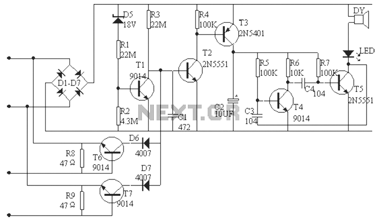
Description: The phone alarm device is designed to monitor and prevent unauthorized use of a telephone line. When interference signals are detected on the line due to theft attempts, the alarm activates, preventing the thief from making calls while alerting the owner through a sound notification. The schematic diagram of this anti-theft device illustrates that the post office typically sends a program-controlled machine with a standby voltage of approximately 60V. Diodes D1-D4 are configured for positive polarity switching. Diode D5 breaks down when the voltage rises at the base of transistor T1 through resistor R2, allowing T1 to conduct and cutting off T2 while T3 is turned off. The oscillation circuit, formed by transistors T4 and T5, remains inactive.
When the telephone line is tampered with, the external voltage drops to about 9V, preventing D5 from breaking down. Consequently, T1 does not receive bias and cuts off, causing T2's base potential to rise and allowing T2 to conduct. This activation turns on T3, which drives the audio-stage oscillation circuit, LED, and DY audible alarm. The LED and DY generate an interference signal on the external line, making it impossible for the thief to complete a call and forcing them to hang up. Although the owner can answer the phone, which reduces the voltage and turns off T1, transistors T6 and T7 (used for ease of installation and allowing polarity-independent connection) still provide base current through the telephone line, ensuring T3 remains off and the oscillation circuit is inactive. This design allows the owner to make normal calls without disruption, as the resistance between the master telephone and the external line (R8, R9) is minimal, ensuring no interference during calls. The electronic components used in the telephone line burglar alarm circuit include general-purpose diodes D1-D4 (e.g., IN4007), an 18V regulator for D5, and a 3V electromagnetic buzzer for DY. Carbon film resistors rated at 1/8W are recommended for the resistances, along with other components as specified in the schematic.
The operational principle of this phone alarm device relies on the monitoring of line voltage and the behavior of the transistors and diodes under varying conditions. The design ensures that the system remains inactive during normal operation while providing robust protection against unauthorized access. The use of common electronic components not only simplifies the construction of the circuit but also makes it cost-effective and easily accessible for implementation. By integrating an audible alarm and visual indicators, the device effectively alerts the owner to potential theft while maintaining the integrity of regular telephone service.Phone alarm device can monitor and prevent unlawful misappropriation of your telephone line. When someone in your telephone line and the machine thefts from outside the alarm on the issue of interference signals, so thieves can not dial, and the light was stolen phone to the owner Tip Sound. The following figure is a schematic diagram of the anti-theft device, usually the post office sends program-controlled machine outside line standby voltage of about 60V, the D1-D4 is positive polarity switch on top, D5 breakdown by R2 enable T1 base potential rises, T1 guide pass, T2 cutoff, T3 is turned off, the oscillation circuit consists of T4, T5 composition does not work. When the phone theft elevator, outside the voltage drop of about 9V, can not make D5 breakdown, T1 because no bias cut, T2 base potential rise conduction.
T2 is turned on so T3 is turned on and driven by the audio-stage oscillation circuit, LED, DY audible alarm, and through the LED, DY interfering signal plus an outside line, while the external voltage is low, so that person can not be stolen phone dial-up and forced to hang up. Although the owner pick up the phone to reduce the voltage, and T1 is turned off but the T6 or T7 (with T6, T7 two tubes for ease of installation, the line can access, regardless of polarity, D6, D7 isolators) by telephone machine to obtain the base current conduction, the T3 is not conducting an oscillation circuit does not work.
Therefore, the owner can dial the normal call is not affected. Because then there is only a very small resistance value between the master telephone with an outside R8, R9 so that when the phone call zero vibration are not affected. Telephone line burglar alarm circuit diagram Selection of electronic components D1-D4, D6, D7 can be used as general IN4007 rectifier, etc., D5 choice about 18V regulator, DY is 3V electromagnetic buzzer.
Resistance can be used carbon film resistor 1 / 8W, and other elements of the model shown in the illustration selected.
When the telephone line is tampered with, the external voltage drops to about 9V, preventing D5 from breaking down. Consequently, T1 does not receive bias and cuts off, causing T2's base potential to rise and allowing T2 to conduct. This activation turns on T3, which drives the audio-stage oscillation circuit, LED, and DY audible alarm. The LED and DY generate an interference signal on the external line, making it impossible for the thief to complete a call and forcing them to hang up. Although the owner can answer the phone, which reduces the voltage and turns off T1, transistors T6 and T7 (used for ease of installation and allowing polarity-independent connection) still provide base current through the telephone line, ensuring T3 remains off and the oscillation circuit is inactive. This design allows the owner to make normal calls without disruption, as the resistance between the master telephone and the external line (R8, R9) is minimal, ensuring no interference during calls. The electronic components used in the telephone line burglar alarm circuit include general-purpose diodes D1-D4 (e.g., IN4007), an 18V regulator for D5, and a 3V electromagnetic buzzer for DY. Carbon film resistors rated at 1/8W are recommended for the resistances, along with other components as specified in the schematic.
The operational principle of this phone alarm device relies on the monitoring of line voltage and the behavior of the transistors and diodes under varying conditions. The design ensures that the system remains inactive during normal operation while providing robust protection against unauthorized access. The use of common electronic components not only simplifies the construction of the circuit but also makes it cost-effective and easily accessible for implementation. By integrating an audible alarm and visual indicators, the device effectively alerts the owner to potential theft while maintaining the integrity of regular telephone service.Phone alarm device can monitor and prevent unlawful misappropriation of your telephone line. When someone in your telephone line and the machine thefts from outside the alarm on the issue of interference signals, so thieves can not dial, and the light was stolen phone to the owner Tip Sound. The following figure is a schematic diagram of the anti-theft device, usually the post office sends program-controlled machine outside line standby voltage of about 60V, the D1-D4 is positive polarity switch on top, D5 breakdown by R2 enable T1 base potential rises, T1 guide pass, T2 cutoff, T3 is turned off, the oscillation circuit consists of T4, T5 composition does not work. When the phone theft elevator, outside the voltage drop of about 9V, can not make D5 breakdown, T1 because no bias cut, T2 base potential rise conduction.
T2 is turned on so T3 is turned on and driven by the audio-stage oscillation circuit, LED, DY audible alarm, and through the LED, DY interfering signal plus an outside line, while the external voltage is low, so that person can not be stolen phone dial-up and forced to hang up. Although the owner pick up the phone to reduce the voltage, and T1 is turned off but the T6 or T7 (with T6, T7 two tubes for ease of installation, the line can access, regardless of polarity, D6, D7 isolators) by telephone machine to obtain the base current conduction, the T3 is not conducting an oscillation circuit does not work.
Therefore, the owner can dial the normal call is not affected. Because then there is only a very small resistance value between the master telephone with an outside R8, R9 so that when the phone call zero vibration are not affected. Telephone line burglar alarm circuit diagram Selection of electronic components D1-D4, D6, D7 can be used as general IN4007 rectifier, etc., D5 choice about 18V regulator, DY is 3V electromagnetic buzzer.
Resistance can be used carbon film resistor 1 / 8W, and other elements of the model shown in the illustration selected.
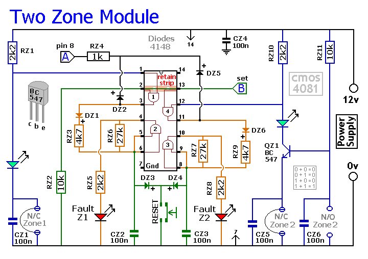
Modular Burglar Alarm
The Basic Alarm Circuit features an automatic Exit/Entry Zone, which includes an Instant Alarm Zone capable of accepting both normally-closed and normally-open triggering devices, alongside an "Always On" 24-hour Personal Attack/Tamper Zone. Expansion Modules can be used to add additional...
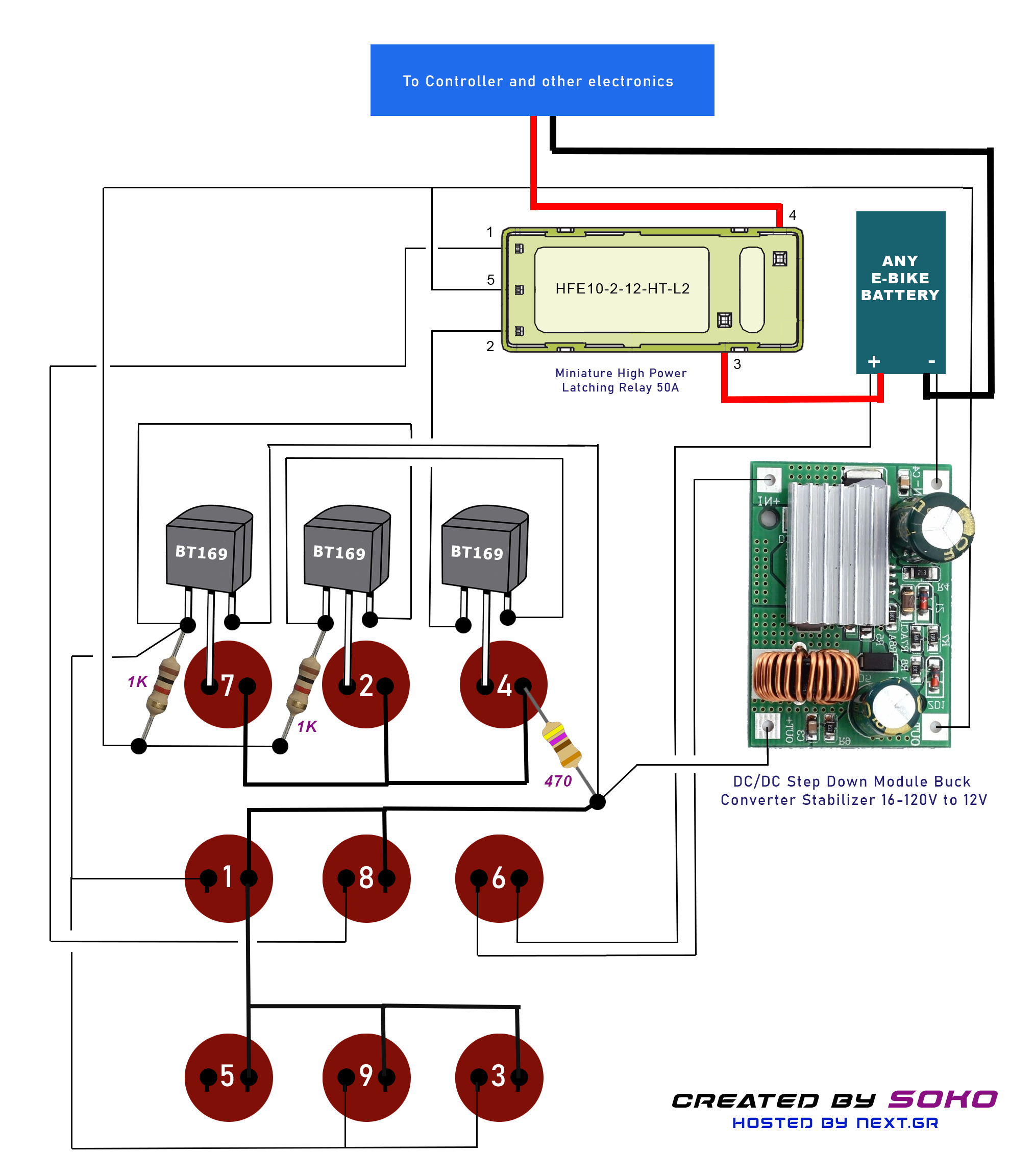
Zero consumption Anti-theft High power Code Switch for E-Bike Batteries
This project is designed for a custom-made battery casing that provides ample space for concealing components. The switch can be adapted for various projects but is specifically tailored to meet e-bike requirements. It utilizes a clever thyristor functionality to create...
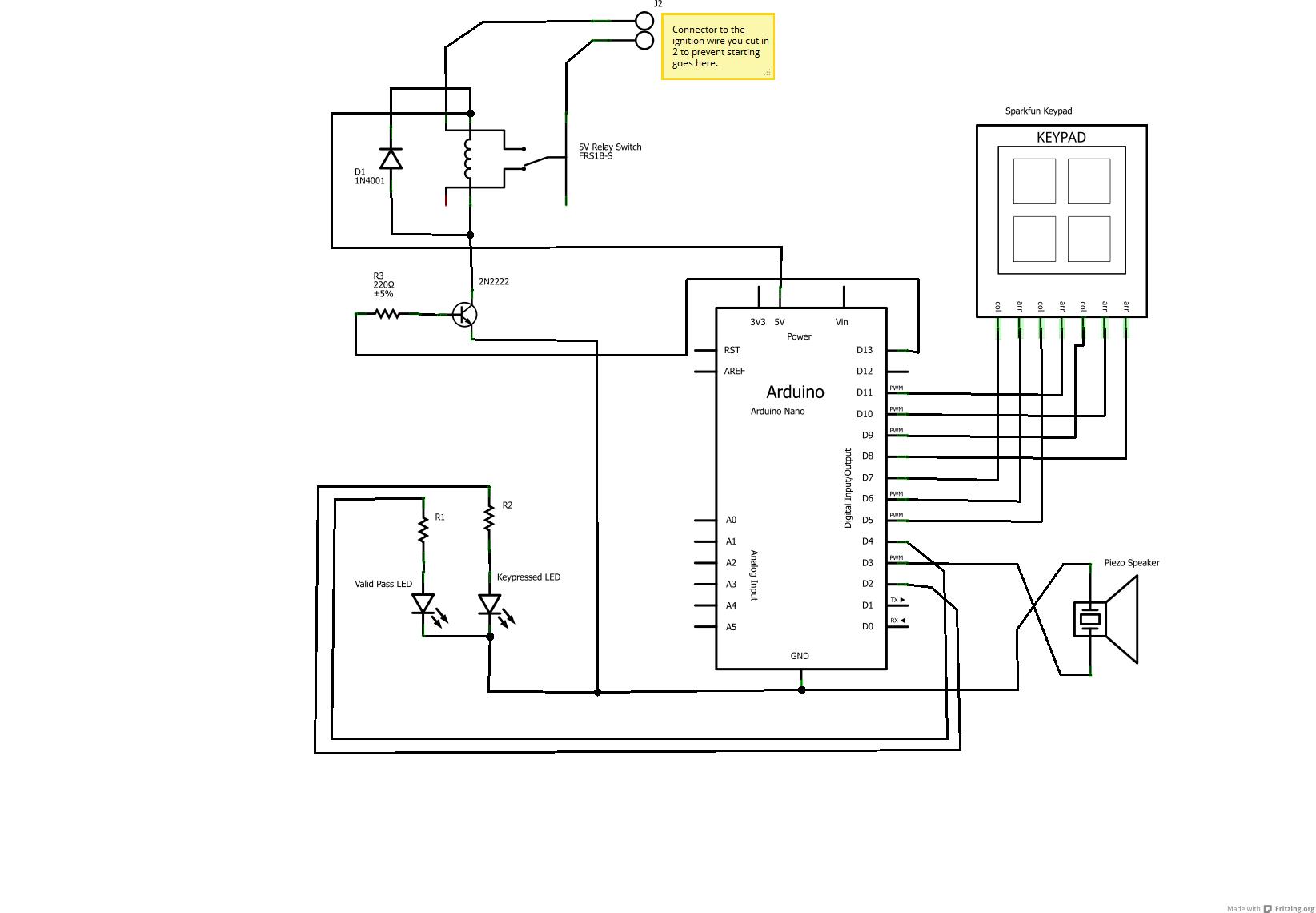
Car Anti-Theft System
Audible signals will alert if the password or keycode entered is accepted or not (in this case, random sounds for incorrect entries and the Super Mario theme for success) using a standard piezo speaker. The under-dashboard USB hub is ideal...
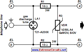
Protection For Telephone Line
A long time ago, when telephones were simple and reliable from an electrical standpoint, telecom operators installed surge protection on all telephone lines exposed to storm risks. Ironically, this protection has diminished as more delicate and expensive equipment, such as...
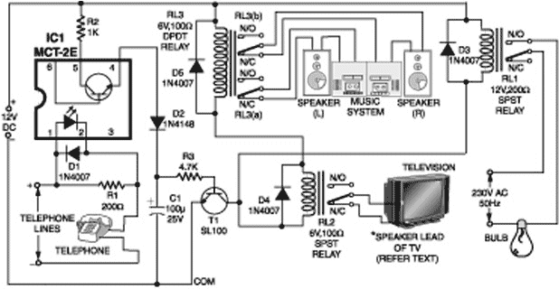
Telephone line based audio muting and light on circuit
A telephone line-based audio muting and light activation circuit. Frequently, when listening to music or watching television at elevated volume levels, it becomes difficult to hear a telephone ring, resulting in missed important calls.
This circuit is designed to address the...
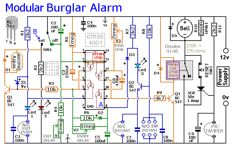
An Expandable Multi-Zone Modular Burglar Alarm circuit
This circuit includes automatic exit and entry delays, as well as a timed bell cut-off feature. It supports both normally-closed and normally-open contacts, and incorporates a 24-hour personal attack/tamper zone. The use of expansion modules allows for the addition of...
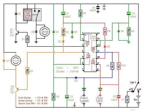
Two-Zone Burglar Alarm
This two-zone alarm features automatic exit, entry, and siren cut-off timers. It was developed for the Beginner's Guide to CMOS Timers, providing a particularly detailed circuit description. An optional One-Time-Only module is available, which will deactivate the siren after the...
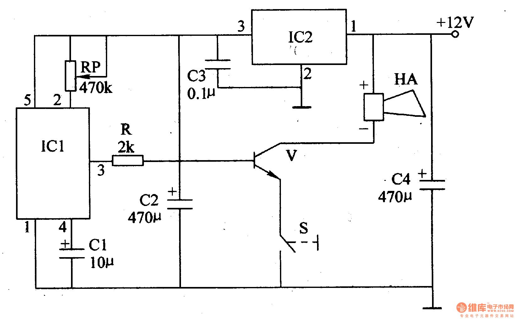
The motorcycle anti-theft alarm (4)
The motorcycle anti-theft alarm described in this article utilizes a proprietary displacement sensor. It is characterized by high sensitivity, good reliability, a low false alarm rate, and ease of construction. The principle of the circuit involves an integrated vibration displacement...
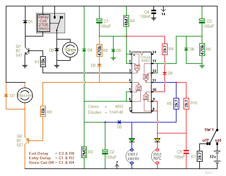
Two-Zone Alarm
This is a two-zone alarm system featuring automatic exit, entry, and siren cut-off timers. It can be activated by standard normally-closed input devices such as magnetic reed contacts, foil tape, and passive infrared sensors (PIRs). The circuit is designed to...