


Temperature Monitor with Alarm
#temperature sensor
#alarm
#monitoring
#thermometer
#energy saving
#buzzer
#temperature threshold
#home automation
#safety
#environmental control

Description: This temperature monitor alarm circuit continuously monitors room temperature and emits a beep when the temperature falls below 20 degrees Celsius. The ability to constantly check the temperature can help reduce air conditioning costs by reminding users to turn off their air conditioner. An optical display, like a thermometer, has limited effectiveness since it can be easily overlooked. In contrast, an audible tone is harder to ignore. The temperature alarm schematic includes R4 as the temperature sensor, specifically a KTY10, although other temperature-dependent resistors can also be utilized in its place. This sensor is integrated into a resistance-bridge circuit powered by 5 volts. The operational amplifier IC1, a CA3130, functions as a bridge amplifier. When the temperature is above the preset threshold set by potentiometers P1 and P2, the output of IC1 remains at 0 volts. If the temperature drops below this threshold, the positive input of IC1 receives increased current, causing the output to swing to 5 volts, which activates the oscillator gate U1. This gate generates a pulse of approximately 0.2 seconds. This pulse subsequently triggers the oscillator gate U3, producing a tone signal through a piezoelectric crystal driven by gate U4. The frequency of the tone signal is around 5 kHz, and the circuit consumes a current of 2 mA, allowing it to be powered by a simple power supply. The sensor should be installed outside the housing to prevent false triggering from the heat of the transformer. For circuit alignment, points A and B must be temporarily shorted to enable the alarm beep. Potentiometer P3 adjusts the volume of the beep, while P1 allows for rough tuning of the desired room temperature, and P2 serves as a fine-tuning control. During normal operation, the short between points A and B should be removed.
The circuit operates on a straightforward principle of temperature monitoring and alarm signaling. The KTY10 temperature sensor serves as the primary sensing element, providing an analog signal that varies with temperature changes. The resistance-bridge configuration allows for precise detection of small variations in resistance, which correspond to temperature fluctuations. The CA3130 operational amplifier amplifies these changes, ensuring that even slight drops in temperature can trigger the alarm.
Upon activation of the alarm, the oscillator gates produce a clear, audible alert. The design allows for flexibility in tuning, accommodating different environmental conditions and user preferences. The use of potentiometers for adjustment enhances user experience, enabling customization of both the alarm threshold and volume. The choice of a piezoelectric crystal for sound generation ensures reliability and clarity of the alarm tone.
The power consumption of 2 mA is relatively low, making this circuit suitable for battery operation or low-power applications. Proper installation of the sensor is crucial to avoid false alarms, emphasizing the importance of thoughtful circuit design in practical applications. Overall, this temperature monitor alarm circuit is an effective solution for maintaining energy efficiency while providing a reliable alert system for temperature management.This temperature monitor alarm circuit continuosly monitors the room temperature and beeps when the temperature drops below 20 degrees centigrade. This capability to constantly monitor the room temperature can help lower your air-conditioning costs by reminding you to turn off your airconditioner.
An optical display like a thermometer has a limite d effectivity since it can be easily overlooked. A tone signal on the other hand is not easy to ignore. Let us look at the temperature alarm schematic. R4 is the temperature sensor KTY10. Other temperature dependent resistor types can also be used in tis place. This sensor is connected to a resistance-bridge circuit and supplied with 5 volts. The IC1 CA3130 works as a bridge amplifier. As long as the temperature is higher than the value preset by P1 and P2, the output of IC1 is 0 volt. Once the temperature drops below the preset value, the plus input of IC1 receives more current and its output level swings to 5 volts, thus switching the oscillator gate U1 on.
This gate creates a pulse of aroung 0. 2 seconds. This pulse in turn switches on the oscillator gate U3. The tone signal is generated by a piezo-electric crystal which is driven by gate U4. Thre frequency of the tone signal is aroung 5 kHz. The current consumption is 2 mA which allows the circuit to be powered by a simple power supply. The sensor must be installed outside the housing so that is will not be falsely triggered by the heat of the transformer. To align the circuit, points A and B must be shorten temporarily so that the alarm beeps. Potentiometer P3 controls the volume of the beep. The chosen room temperature can be roughly tuned by P1. P2 is used as a fine tuner. In normal operation, remove the short between points A and B.
The circuit operates on a straightforward principle of temperature monitoring and alarm signaling. The KTY10 temperature sensor serves as the primary sensing element, providing an analog signal that varies with temperature changes. The resistance-bridge configuration allows for precise detection of small variations in resistance, which correspond to temperature fluctuations. The CA3130 operational amplifier amplifies these changes, ensuring that even slight drops in temperature can trigger the alarm.
Upon activation of the alarm, the oscillator gates produce a clear, audible alert. The design allows for flexibility in tuning, accommodating different environmental conditions and user preferences. The use of potentiometers for adjustment enhances user experience, enabling customization of both the alarm threshold and volume. The choice of a piezoelectric crystal for sound generation ensures reliability and clarity of the alarm tone.
The power consumption of 2 mA is relatively low, making this circuit suitable for battery operation or low-power applications. Proper installation of the sensor is crucial to avoid false alarms, emphasizing the importance of thoughtful circuit design in practical applications. Overall, this temperature monitor alarm circuit is an effective solution for maintaining energy efficiency while providing a reliable alert system for temperature management.This temperature monitor alarm circuit continuosly monitors the room temperature and beeps when the temperature drops below 20 degrees centigrade. This capability to constantly monitor the room temperature can help lower your air-conditioning costs by reminding you to turn off your airconditioner.
An optical display like a thermometer has a limite d effectivity since it can be easily overlooked. A tone signal on the other hand is not easy to ignore. Let us look at the temperature alarm schematic. R4 is the temperature sensor KTY10. Other temperature dependent resistor types can also be used in tis place. This sensor is connected to a resistance-bridge circuit and supplied with 5 volts. The IC1 CA3130 works as a bridge amplifier. As long as the temperature is higher than the value preset by P1 and P2, the output of IC1 is 0 volt. Once the temperature drops below the preset value, the plus input of IC1 receives more current and its output level swings to 5 volts, thus switching the oscillator gate U1 on.
This gate creates a pulse of aroung 0. 2 seconds. This pulse in turn switches on the oscillator gate U3. The tone signal is generated by a piezo-electric crystal which is driven by gate U4. Thre frequency of the tone signal is aroung 5 kHz. The current consumption is 2 mA which allows the circuit to be powered by a simple power supply. The sensor must be installed outside the housing so that is will not be falsely triggered by the heat of the transformer. To align the circuit, points A and B must be shorten temporarily so that the alarm beeps. Potentiometer P3 controls the volume of the beep. The chosen room temperature can be roughly tuned by P1. P2 is used as a fine tuner. In normal operation, remove the short between points A and B.
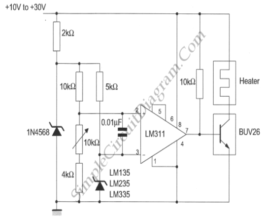
Simple Temperature Controller
This temperature controller utilizes an LM135/235/335 temperature sensor and is designed to maintain a small environment at a warm or hot temperature. A schematic diagram is provided.
The temperature controller circuit is centered around the LM135/235/335 series of temperature sensors, which...

Hot Tub Hack
This modification replaces the thermistor (temperature sensor) of a hot tub with an adjustable resistor that deceives the hot tub controller into believing the water is at a specific temperature. Additionally, the circuit is activated and deactivated by a 24VAC...
temp control circuit
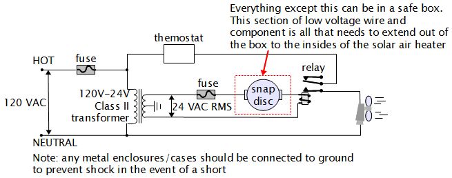
For various experiments, such as solar air heaters, an automatic fan activation and deactivation system is required. A straightforward solution is to use a bimetal snap disc thermal sensor. This sensor functions as a switch that closes when a specific...
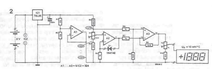
Thermometer circuit schematic using operational amplifiers
A simple thermometer can be constructed using operational amplifiers and a standard or protective diode, such as the 1N4148, as depicted in the electronic diagram below. A constant reference voltage is supplied to the non-inverting input of the operational amplifier....
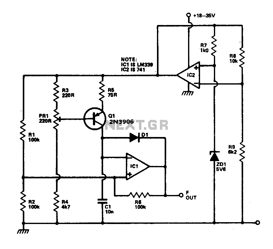
Linear temperature-to-frequency
This circuit provides a linear frequency increase of 10 Hz per °C over a temperature range of 0 to 100 °C and can be utilized with logic systems, including microprocessors. The temperature probe Q1, utilizing the Vbe characteristic, changes by...
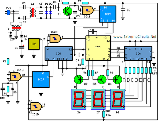
Digital Remote Thermometer
This circuit is designed for precise measurement of temperature in degrees Celsius. It features a transmitter section that converts the output voltage from a temperature sensor, which is proportional to the temperature being measured, into frequency. The resulting frequency bursts...
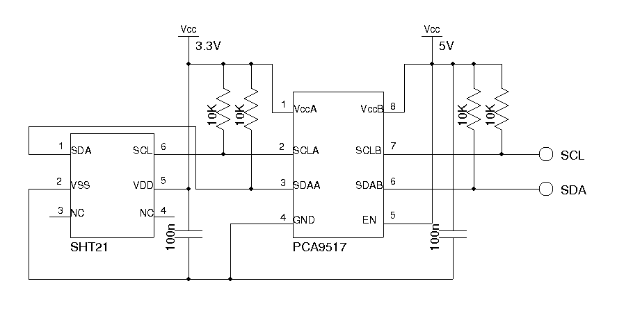
A Dual Temperature Display With Humidity Measurement
This thermometer employs an LM19 sensor, calibrated to measure a broad temperature range of -55 to 130 degrees Celsius (-67 to 266 degrees Fahrenheit) for outdoor temperature readings. For indoor temperature and humidity measurements, it utilizes an SHT21 digital sensor....
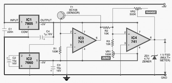
DIY Digital Thermometer Circuit
This DIY digital thermometer circuit can measure temperatures up to 150°C with an accuracy of ±1°C. The temperature is displayed on a 1V full scale deflection.
The digital thermometer circuit is designed to provide accurate temperature readings within a specified range,...
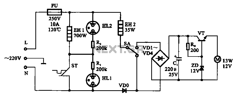
Electric thermos temperature detection control circuit
The electric thermos temperature detection control circuit is designed to monitor and manage the temperature within an electric thermos. It primarily consists of a control circuit for the boiler heater and heater insulation, an electrical magnetic pump motor drive circuit,...