


TYN612 SENSITIVE & STANDARD(12A SCRs)
#burglar alarm
#SCR
#transistor
#window foil
#home security
#sensor
#BC107
#TYN612
#circuit protection
#intrusion detection
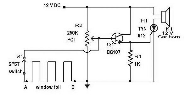
Description: The circuit diagram of a window foil burglar alarm is presented here. The main components of this circuit are SCR H1 (TYN 612) and transistor Q1 (BC 107). This burglar alarm can be installed in windows to detect attempts of breaking in. The sensing element for detecting a break attempt is a network. This simple burglar alarm circuit is designed to protect homes and gardens from burglary activities. In today's context, there is no place in the world where crime does not exist. This straightforward circuit can be utilized to prevent illegal entry into homes and gardens.
The window foil burglar alarm circuit utilizes a combination of components to create an effective security solution. The SCR (Silicon Controlled Rectifier) H1 (TYN 612) acts as a switch that is triggered when a break in the foil network occurs. The transistor Q1 (BC 107) serves as an amplifier, enhancing the signal generated by the break in the circuit. When the foil is cut or disturbed, it creates a voltage change that activates the SCR, which then can trigger an alarm or other alerting mechanism.
The circuit is designed to be simple, making it accessible for DIY enthusiasts and homeowners looking to enhance their security without incurring significant costs. The foil, which serves as the sensing element, can be easily affixed to the window frame, creating an invisible barrier that is difficult to bypass without detection.
In addition, this circuit can be integrated with other security systems, allowing for a comprehensive approach to home security. The use of a transistor in the design allows for the incorporation of additional features, such as a visual indicator (LED) or a siren, to alert occupants of a potential breach.
This burglar alarm circuit exemplifies the importance of simple yet effective solutions in home security, providing peace of mind in an increasingly uncertain world. Its design can be adapted for various applications, including securing garden sheds or other vulnerable areas.Circuit The circuit diagram of window foil burglar alarm has been published here. The main parts of this circuit are SCR H1 (TYN 612) and transistor Q1 (BC 107). This burglar alarm can be fitted in windows to check breaking attempts. Here the sensing element of break attempt is a network. This is a simple Burglar Alarm Circuit (home se curity) to protect your home/garden from burglary activity. In present contest there is no such place in the world where crime doesn’t exist. This simple circuit can be used to avoid illegal entry inside your home/garden. I prefer this circuit. This 8 function serial Christmas lamp controller is based on the IC UTC 8156 from Unisonic. Specially designed for the same purpose, the UTC 8156 can control the four lamps in 8 modes namely waves, sequential, slo-gol, chasing/flash, slow fade, twinkle/flash, steady ON and auto scan. Con.
The window foil burglar alarm circuit utilizes a combination of components to create an effective security solution. The SCR (Silicon Controlled Rectifier) H1 (TYN 612) acts as a switch that is triggered when a break in the foil network occurs. The transistor Q1 (BC 107) serves as an amplifier, enhancing the signal generated by the break in the circuit. When the foil is cut or disturbed, it creates a voltage change that activates the SCR, which then can trigger an alarm or other alerting mechanism.
The circuit is designed to be simple, making it accessible for DIY enthusiasts and homeowners looking to enhance their security without incurring significant costs. The foil, which serves as the sensing element, can be easily affixed to the window frame, creating an invisible barrier that is difficult to bypass without detection.
In addition, this circuit can be integrated with other security systems, allowing for a comprehensive approach to home security. The use of a transistor in the design allows for the incorporation of additional features, such as a visual indicator (LED) or a siren, to alert occupants of a potential breach.
This burglar alarm circuit exemplifies the importance of simple yet effective solutions in home security, providing peace of mind in an increasingly uncertain world. Its design can be adapted for various applications, including securing garden sheds or other vulnerable areas.Circuit The circuit diagram of window foil burglar alarm has been published here. The main parts of this circuit are SCR H1 (TYN 612) and transistor Q1 (BC 107). This burglar alarm can be fitted in windows to check breaking attempts. Here the sensing element of break attempt is a network. This is a simple Burglar Alarm Circuit (home se curity) to protect your home/garden from burglary activity. In present contest there is no such place in the world where crime doesn’t exist. This simple circuit can be used to avoid illegal entry inside your home/garden. I prefer this circuit. This 8 function serial Christmas lamp controller is based on the IC UTC 8156 from Unisonic. Specially designed for the same purpose, the UTC 8156 can control the four lamps in 8 modes namely waves, sequential, slo-gol, chasing/flash, slow fade, twinkle/flash, steady ON and auto scan. Con.
Shed/Garage Alarm
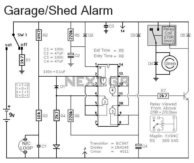
This is a simple single-zone burglar alarm circuit. Its features include automatic exit and entry delays. It is designed to be used with the usual types of normally-closed input devices such as magnetic reed contacts, micro switches, foil tape, and...
SCR_LATCH
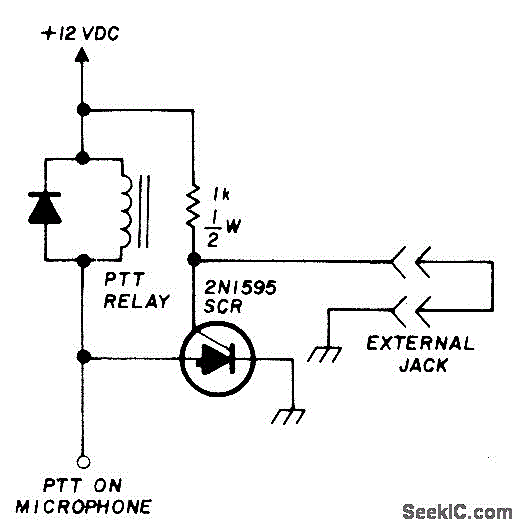
Activates a mobile transceiver or other mobile equipment when power is applied, especially if the external circuit is interrupted during theft. The transmitter will then emit an unmodulated carrier signal even if the Push-To-Talk (PTT) switch is disconnected or turned...
SCR UJI TIME DELAY
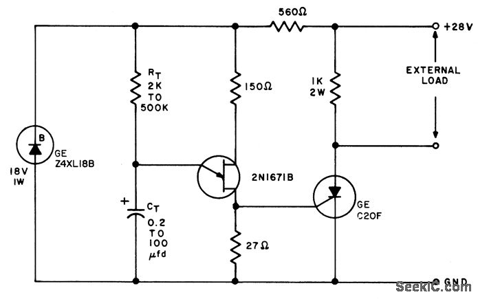
The timing interval is initiated by applying power and is determined by the resistor-capacitor (RT-CT) combination. At the end of the interval, a unijunction transistor triggers a silicon controlled rectifier (SCR) to apply nearly the full supply voltage to the...
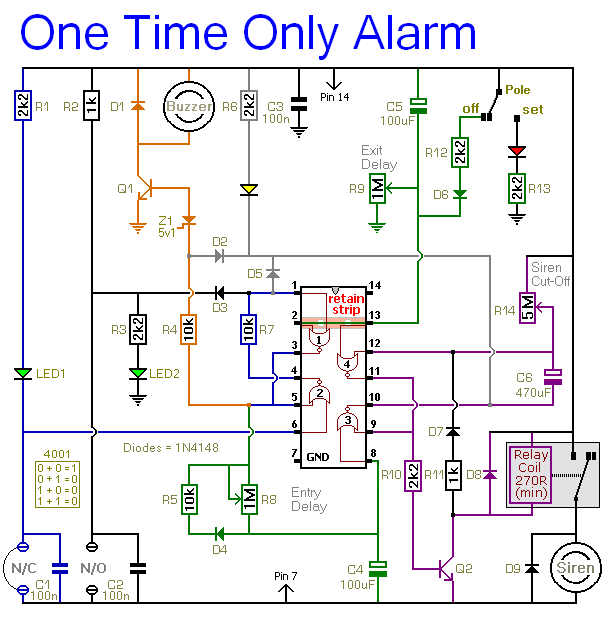
How To Build A One-Time-Only >> Burglar Alarm Circuit
This alarm is designed to activate its siren only once. When the alarm is triggered, the siren will sound for a predetermined duration before automatically turning off and remaining inactive. The alarm system features a single zone with independently adjustable...
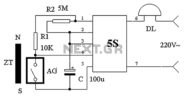
Burglar alarm bell
The circuit operates based on the principle of a shaped permanent magnet mounted on the door, referred to as ZT, and a normally closed reed switch, labeled AG, mounted on the door frame. Under normal conditions, ZT is in close...
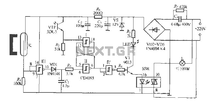
Gate automatic lamp circuit
The circuit utilizes multiple integrated circuits to form an automatic lighting device that is activated by door and window sensors. It includes CD4093 digital integrated circuits, a relay, and a power supply circuit. The system typically remains closed when a...
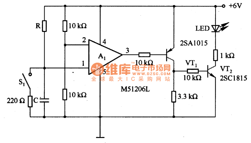
The time delay circuit diagram composed of transistor
The circuit is designed to set a delay time based on the voltage Us and the resistor R. In this configuration, S1 acts as the discharge switch for capacitor C. When switch S1 is closed, the stored charge in capacitor...
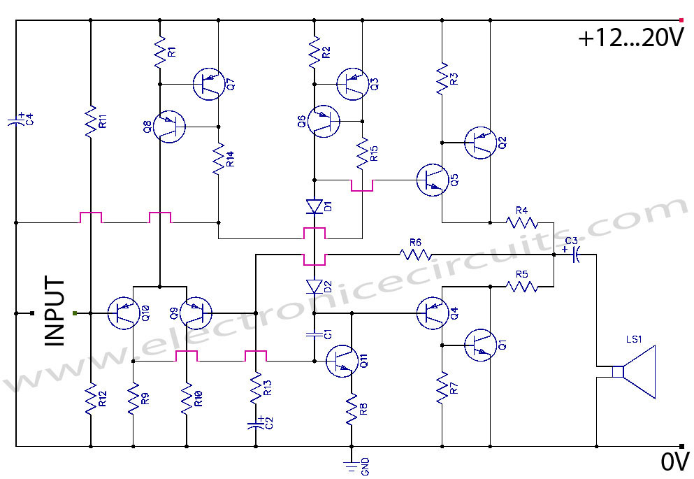
transistor power amplifier circuit diagram
Discrete Class AB Transistor Audio Power Amplifier Circuit Diagram. This is a Class AB transistor power amplifier. It is a simple amplifier to...
A Class AB transistor audio power amplifier is designed to provide high-quality amplification for audio signals while maintaining...
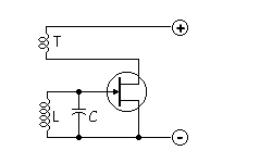
Tickler oscillator circuit
When the circuit is initially powered, neither transistor is activated, resulting in high base voltages for both and a tendency to turn on. Due to slight asymmetries, one transistor will activate first, leading the circuit into one of its states...