


UltraSonic Radars
#ultrasonic
#sensor
#alarm
#security
#motion detection
#home automation
#transmitter
#receiver
#automotive
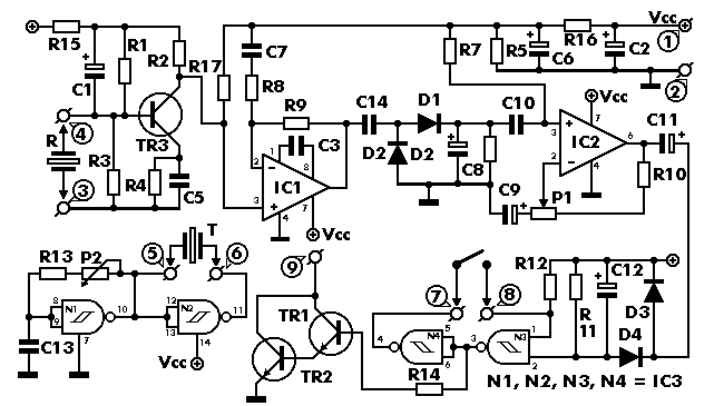
Description: This project has numerous practical applications in security and alarm systems for homes, shops, and vehicles. It features a set of ultrasonic transmitter and receiver operating at the same frequency. When an object moves within the area covered by the circuit, the circuit's balance is disrupted, triggering the alarm. The circuit is highly sensitive and can be configured to reset automatically or require manual reset after an alarm. The ultrasonic transmitter and receiver utilize piezoelectric transducers as output and input devices, respectively, with their operating frequency determined by the specific devices employed. The transmitter is designed using two NAND gates from IC3, configured as inverters, forming a multivibrator whose output drives the transducer. A trimmer, P2, adjusts the transmitter's output frequency, which should match the resonance frequency of the transducers for optimal performance. The receiver employs a transducer to capture reflected signals, which are amplified by transistor TR3 and IC1, a 741 op-amp. The output from IC1 is directed to the non-inverting input of IC2, with the amplification factor adjustable via P1. The circuit maintains balance as long as the transmitter's output frequency remains unchanged. Any movement in the ultrasonic emission area distorts the reflected signal, disrupting the circuit balance. This abrupt change at the output of IC2 triggers the Schmitt trigger circuit, built using the remaining two gates in IC3, activating output transistors TR1 and TR2, which signal the alarm system or activate a relay connected in series with TR1's collector. The circuit operates on 9-12 VDC and can be powered by batteries or an external power supply.
Building electronic circuits on a printed circuit board (PCB) involves several fundamental principles. The PCB is composed of a thin insulating material coated with a thin layer of conductive copper, forming the necessary pathways between various circuit components. A well-designed PCB is advantageous as it accelerates construction and minimizes errors. Smart Kit boards are pre-drilled with component outlines and identifications printed on the component side to facilitate assembly. To prevent oxidation during storage and ensure pristine delivery, the copper is tinned during manufacturing and covered with a protective varnish that also eases soldering. Soldering components to the board is essential for circuit assembly, and the technique significantly impacts the project's success. The soldering iron must be lightweight, with a power rating not exceeding 25 watts. A fine tip should be maintained clean, using specially designed wet sponges to wipe off accumulated residues. If the tip cannot be cleaned, it should be replaced rather than filed or sanded. Choosing a high-quality solder containing the necessary flux in its core is crucial for achieving reliable joints.This is a very interesting project with many practical applications in security and alarm systems for homes, shops and cars. It consists of a set of ultrasonic receiver and transmitter which operate at the same frequency. When something moves in the area covered by the circuit the circuit ’s fine balance is disturbed and the alarm is triggered.
Th e circuit is very sensitive and can be adjusted to reset itself automatically or to stay triggered till it is reset manually after an alarm. As it has already been stated the circuit consists of an ultrasonic transmitter and a receiver both of which work at the same frequency.
They use ultrasonic piezoelectric transducers as output and input devices respectively and their frequency of operation is determined by the particular devices in use. The transmitter is built around two NAND gates of the four found in IC3 which are used here wired as inverters and in the particular circuit they form a multivibrator the output of which drives the transducer.
The trimmer P2 adjusts the output frequency of the transmitter and for greater efficiency it should be made the same as the frequency of resonance of the transducers in use. The receiver similarly uses a transducer to receive the signals that are reflected back to it the output of which is amplified by the transistor TR3, and IC1 which is a 741 op-amp.
The output of IC1 is taken to the non inverting input of IC2 the amplification factor of which is adjusted by means of P1. The circuit is adjusted in such a way as to stay in balance as long the same as the output frequency of the transmitter.
If there is some movement in the area covered by the ultrasonic emission the signal that is reflected back to the receiver becomes distorted and the circuit is thrown out of balance. The output of IC2 changes abruptly and the Schmitt trigger circuit which is built around the remaining two gates in IC3 is triggered.
This drives the output transistors TR1, 2 which in turn give a signal to the alarm system or if there is a relay connected to the circuit, in series with the collector of TR1, it becomes activated. The circuit works from 9-12 VDC and can be used with batteries or a power supply. First of all let us consider a few basics in building electronic circuits on a printed circuit board.
The board is made of a thin insulating material clad with a thin layer of conductive copper that is shaped in such a way as to form the necessary conductors between the various components of the circuit. The use of a properly designed printed circuit board is very desirable as it speeds construction up considerably and reduces the possibility of making errors.
Smart Kit boards also come pre-drilled and with the outline of the components and their identification printed on the component side to make construction easier. To protect the board during storage from oxidation and assure it gets to you in perfect condition the copper is tinned during manufacturing and covered with a special varnish that protects it from getting oxidised and also makes soldering easier.
Soldering the components to the board is the only way to build your circuit and from the way you do it depends greatly your success or failure. This work is not very difficult and if you stick to a few rules you should have no problems. The soldering iron that you use must be light and its power should not exceed the 25 Watts. The tip should be fine and must be kept clean at all times. For this purpose come very handy specially made sponges that are kept wet and from time to time you can wipe the hot tip on them to remove all the residues that tend to accumulate on it.
DO NOT file or sandpaper a dirty or worn out tip. If the tip cannot be cleaned, replace it. There are many different types of solder in the market and you should choose a good quality one that contains the necessary flux in its core, to assure a perfect joint every time. DO NOT use so
Building electronic circuits on a printed circuit board (PCB) involves several fundamental principles. The PCB is composed of a thin insulating material coated with a thin layer of conductive copper, forming the necessary pathways between various circuit components. A well-designed PCB is advantageous as it accelerates construction and minimizes errors. Smart Kit boards are pre-drilled with component outlines and identifications printed on the component side to facilitate assembly. To prevent oxidation during storage and ensure pristine delivery, the copper is tinned during manufacturing and covered with a protective varnish that also eases soldering. Soldering components to the board is essential for circuit assembly, and the technique significantly impacts the project's success. The soldering iron must be lightweight, with a power rating not exceeding 25 watts. A fine tip should be maintained clean, using specially designed wet sponges to wipe off accumulated residues. If the tip cannot be cleaned, it should be replaced rather than filed or sanded. Choosing a high-quality solder containing the necessary flux in its core is crucial for achieving reliable joints.This is a very interesting project with many practical applications in security and alarm systems for homes, shops and cars. It consists of a set of ultrasonic receiver and transmitter which operate at the same frequency. When something moves in the area covered by the circuit the circuit ’s fine balance is disturbed and the alarm is triggered.
Th e circuit is very sensitive and can be adjusted to reset itself automatically or to stay triggered till it is reset manually after an alarm. As it has already been stated the circuit consists of an ultrasonic transmitter and a receiver both of which work at the same frequency.
They use ultrasonic piezoelectric transducers as output and input devices respectively and their frequency of operation is determined by the particular devices in use. The transmitter is built around two NAND gates of the four found in IC3 which are used here wired as inverters and in the particular circuit they form a multivibrator the output of which drives the transducer.
The trimmer P2 adjusts the output frequency of the transmitter and for greater efficiency it should be made the same as the frequency of resonance of the transducers in use. The receiver similarly uses a transducer to receive the signals that are reflected back to it the output of which is amplified by the transistor TR3, and IC1 which is a 741 op-amp.
The output of IC1 is taken to the non inverting input of IC2 the amplification factor of which is adjusted by means of P1. The circuit is adjusted in such a way as to stay in balance as long the same as the output frequency of the transmitter.
If there is some movement in the area covered by the ultrasonic emission the signal that is reflected back to the receiver becomes distorted and the circuit is thrown out of balance. The output of IC2 changes abruptly and the Schmitt trigger circuit which is built around the remaining two gates in IC3 is triggered.
This drives the output transistors TR1, 2 which in turn give a signal to the alarm system or if there is a relay connected to the circuit, in series with the collector of TR1, it becomes activated. The circuit works from 9-12 VDC and can be used with batteries or a power supply. First of all let us consider a few basics in building electronic circuits on a printed circuit board.
The board is made of a thin insulating material clad with a thin layer of conductive copper that is shaped in such a way as to form the necessary conductors between the various components of the circuit. The use of a properly designed printed circuit board is very desirable as it speeds construction up considerably and reduces the possibility of making errors.
Smart Kit boards also come pre-drilled and with the outline of the components and their identification printed on the component side to make construction easier. To protect the board during storage from oxidation and assure it gets to you in perfect condition the copper is tinned during manufacturing and covered with a special varnish that protects it from getting oxidised and also makes soldering easier.
Soldering the components to the board is the only way to build your circuit and from the way you do it depends greatly your success or failure. This work is not very difficult and if you stick to a few rules you should have no problems. The soldering iron that you use must be light and its power should not exceed the 25 Watts. The tip should be fine and must be kept clean at all times. For this purpose come very handy specially made sponges that are kept wet and from time to time you can wipe the hot tip on them to remove all the residues that tend to accumulate on it.
DO NOT file or sandpaper a dirty or worn out tip. If the tip cannot be cleaned, replace it. There are many different types of solder in the market and you should choose a good quality one that contains the necessary flux in its core, to assure a perfect joint every time. DO NOT use so
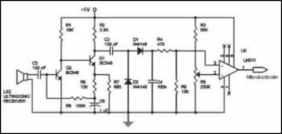
Ultrasonic Wave Receiver Circuit Schematic Diagram
Ultrasonic receivers detect an ultrasonic signal emitted by an ultrasonic transmitter at a specific frequency. The received signal is filtered using a band-pass filter circuit that allows only the predetermined frequency range to pass. The output signal is then amplified...
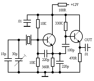
80M
This 80M receiver design incorporates the necessary switching mechanisms to enable the SSB filter and first intermediate frequency (I.F.) amplifier to function for transmission purposes. The receiver stages, from the radio frequency (R.F.) input to the speaker output, will be...
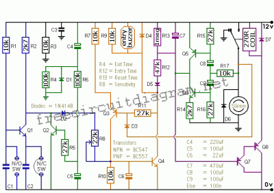
Single Alarm Circuit
This is a single alarm circuit. The circuit includes automatic exit and entry delays, a timed bell cut-off, and a system reset. It has provisions for normally open and normally closed inputs.
The single alarm circuit is designed to provide security...
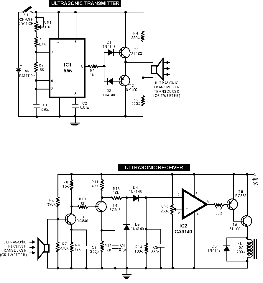
Ultrasonic switch circuit
This circuit functions with inaudible (ultrasonic) sound. Sound of frequency up to 20 kHz is audible to human beings. The sound of frequency above 20 kHz is called ultrasonic sound. The circuit described generates (transmits) ultrasonic sound of frequency between...
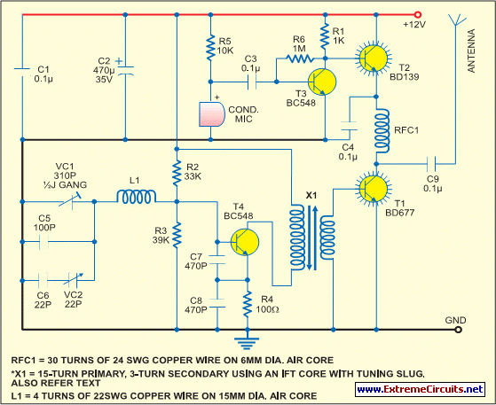
Simple Short-Wave Transmitter
This low-cost short-wave transmitter is tunable from 10 to 15 MHz using a ½J gang condenser VC1, which sets the carrier frequency in conjunction with inductor L1. Frequency trimming is achieved with VC2. The carrier signal is amplified by transistor...
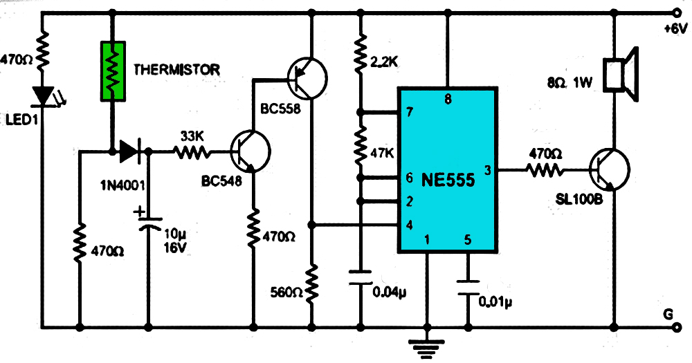
Alarm
This is a simple and easy-to-build multi-tone alarm circuit that can be utilized in burglar alarms or sirens. The circuit is based on the dual op-amp MC1458 and LM380. The two op-amps within the MC1458 are configured to generate square...
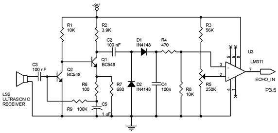
ultrasonic distance measurer
Techniques for an echo sounder used to measure ocean depth can be implemented with an ultrasonic distance measuring device. This device uses a circuit similar to the one described in the previous article, which includes a series of ultrasonic transmitter...
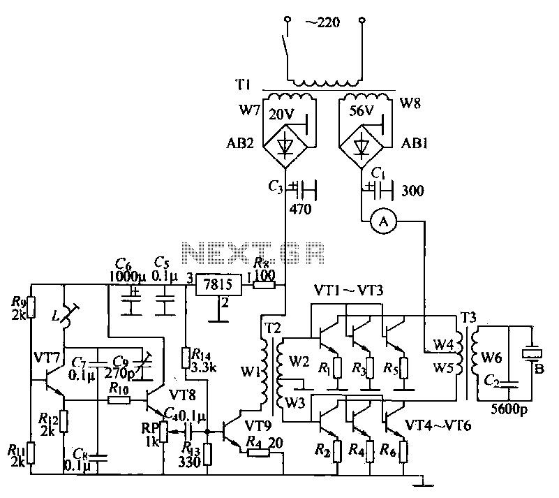
Ultrasonic drilling machine circuit
The ultrasonic drilling machine is essential machinery in the dairy industry for processing jewelry, primarily for natural stones, crystal agate, jade, and glass products. This machine is particularly effective for high-hardness materials, enabling both drilling and engraving. The following outlines...
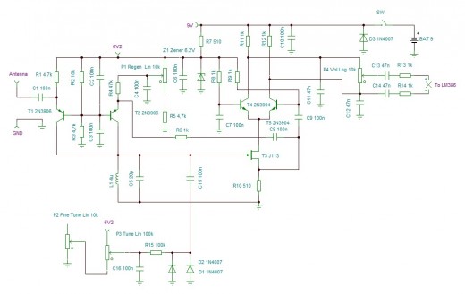
High Performance Regen Receiver
A new high-performance regenerative receiver is available as a kit. The inclusion of an innovative regenerative detector circuit enhances sensitivity and overall performance.
The regenerative receiver kit is designed to provide users with a high-quality radio frequency (RF) reception experience. The...