


Water Alarm Circuit
#water sensor
#555 timer
#astable multivibrator
#alarm circuit
#1kHz tone
#security
#detection
#sensor circuit
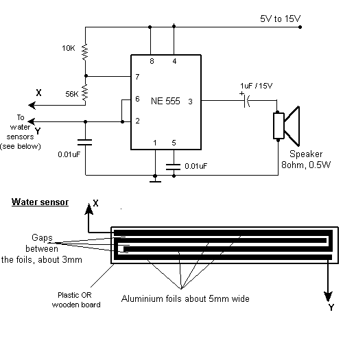
Description: This circuit activates an alarm when its sensor comes into contact with water. It employs a 555 astable multivibrator that generates a tone of approximately 1 kHz upon water detection.
The circuit consists of a 555 timer configured in astable mode, which continuously oscillates to produce a square wave output. The frequency of this output can be adjusted by selecting appropriate resistor and capacitor values connected to the 555 timer. In this application, the output frequency is set to around 1 kHz, which corresponds to a tone that can be easily recognized as an alarm sound.
The sensor component, typically a pair of conductive probes, is placed in a position where it can detect the presence of water. When water bridges the gap between the probes, it completes the circuit, triggering the 555 timer. The output of the timer is connected to a speaker or buzzer, which emits the audible alarm.
To ensure reliable operation, it is crucial to select the right resistors and capacitors for the desired frequency and to consider the sensitivity of the sensor. Additionally, incorporating a diode may be beneficial to protect the circuit from potential back EMF generated by the buzzer.
Power supply considerations should also be addressed, as the circuit typically operates on a low voltage, often supplied by batteries or a DC power source. Proper grounding and layout design will enhance the circuit's performance and longevity. Overall, this water detection alarm circuit provides an effective solution for alerting users to the presence of water through a simple yet efficient electronic design.This circuit gives out an alarm when its sensor is wetted by water. A 555 astable multivibrator is used here which gives a tone of about 1kHz upon detecting water. ..
The circuit consists of a 555 timer configured in astable mode, which continuously oscillates to produce a square wave output. The frequency of this output can be adjusted by selecting appropriate resistor and capacitor values connected to the 555 timer. In this application, the output frequency is set to around 1 kHz, which corresponds to a tone that can be easily recognized as an alarm sound.
The sensor component, typically a pair of conductive probes, is placed in a position where it can detect the presence of water. When water bridges the gap between the probes, it completes the circuit, triggering the 555 timer. The output of the timer is connected to a speaker or buzzer, which emits the audible alarm.
To ensure reliable operation, it is crucial to select the right resistors and capacitors for the desired frequency and to consider the sensitivity of the sensor. Additionally, incorporating a diode may be beneficial to protect the circuit from potential back EMF generated by the buzzer.
Power supply considerations should also be addressed, as the circuit typically operates on a low voltage, often supplied by batteries or a DC power source. Proper grounding and layout design will enhance the circuit's performance and longevity. Overall, this water detection alarm circuit provides an effective solution for alerting users to the presence of water through a simple yet efficient electronic design.This circuit gives out an alarm when its sensor is wetted by water. A 555 astable multivibrator is used here which gives a tone of about 1kHz upon detecting water. ..
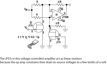
Create a flash-then-steady LED using a 555 timer
The circuit illustrated briefly flashes an LED to attract attention and remains illuminated as long as power is supplied. The circuit utilizes the well-known 555 timer integrated circuit (IC) configured as a standard astable multivibrator with resistors RA, RB, and...
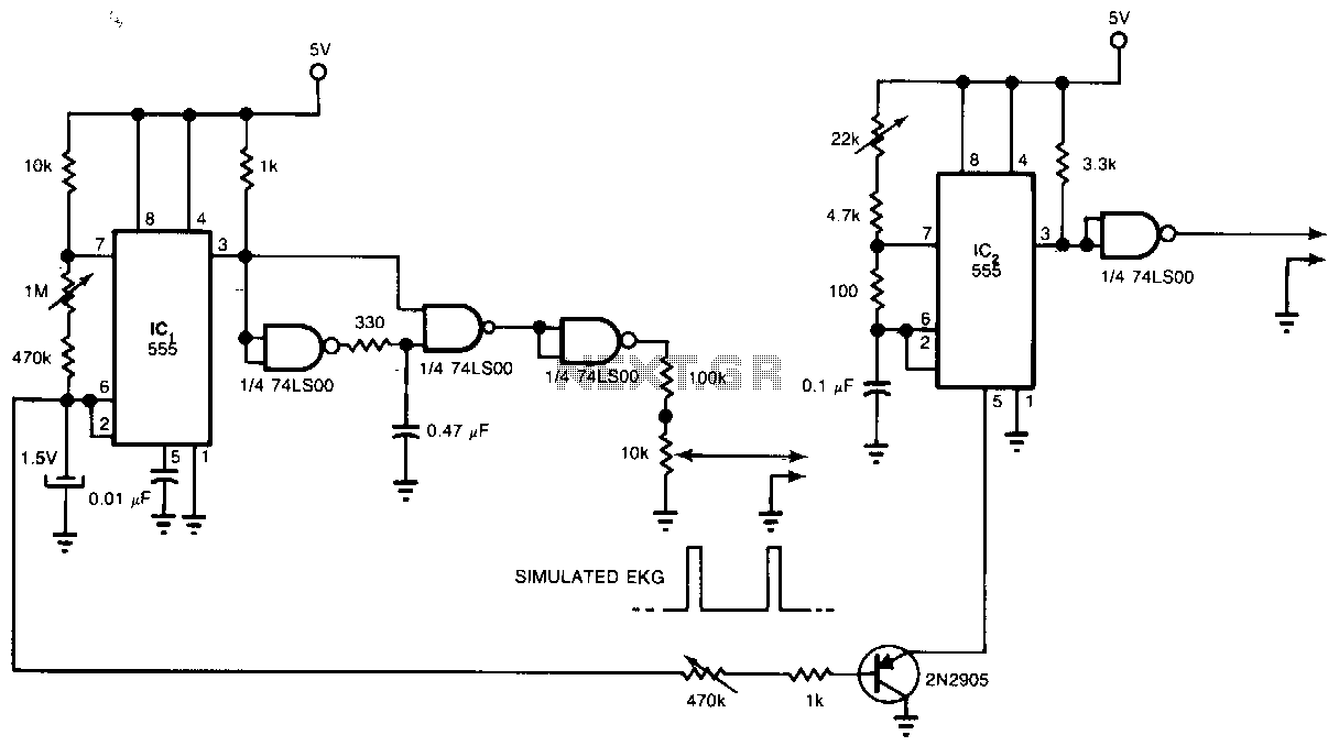
Three-chip-ekg-simulator
Two 555 timers and a quad NAND-gate integrated circuit can simulate an electrocardiograph (EKG) signal and a gamma-ray radioisotope signal for applications in nuclear medicine. This circuit synchronizes the radioisotope signal to the EKG signal. The outputs of the circuit...
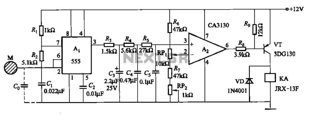
One of capacitive sensing oscillator circuit burglar alarm
The circuit utilizes a 555 IC in conjunction with capacitors C1, C2, and a metal plate (tablet) M to create a distributed capacitance Co and resistor R1 connected to ground. Resistor R2 forms a self-excited multivibrator, while resistors R3 and...
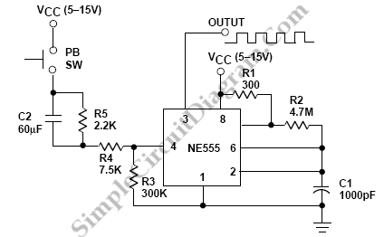
555 IC for Square Wave Tone Burst Generator
Square wave tone bursts are generated by pressing the pushbutton. The duration of these bursts is determined by how long the voltage at Pin 4 exceeds a specified threshold.
The circuit described involves a square wave generator that produces tone bursts...
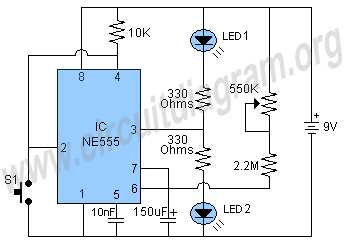
555 timer circuit
The schematic shown below is a 555 timer circuit. The NE555 is a well-known integrated circuit that comes in an 8-pin dual in-line package (DIP). There is a vast array of circuits utilizing the 555 IC, which contributes to its...
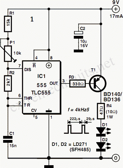
Infra-red Light Barrier Using 555
This is a short-range light barrier designed for use as an intruder alarm in doorposts and similar applications. The 555 timer in the transmitter oscillates at approximately 4.5 kHz.
The short-range light barrier operates by utilizing a transmitter and a receiver...
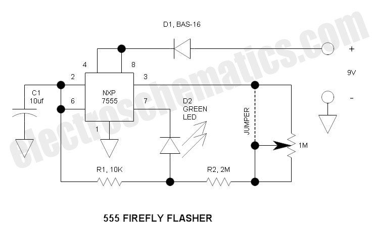
555 Christmas Lights Project
This circuit differs from the standard 555 oscillator circuit by placing the LED in the capacitor reset line (pin 7). This configuration reduces overall current and prevents high peak LED current from draining the battery. The forward voltage drop of...
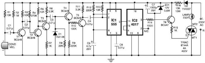
555 Timer Clap Switch
This 555 timer clap switch circuit electronic project is designed using common electronic components.
The 555 timer clap switch circuit utilizes a 555 timer IC in a monostable configuration to create a sound-activated switch. The circuit is triggered by a...
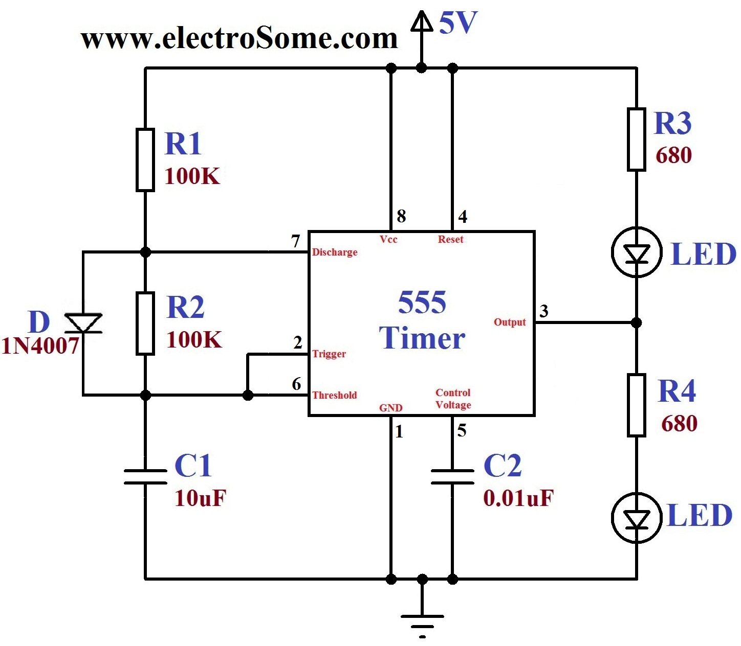
dancing light using 555 timer
A dancing light can be easily constructed using a 555 timer wired in astable mode. This circuit alternately blinks two LEDs with a certain delay and can be modified to include additional LEDs or to control incandescent lamps. The oscillation...