


water sensor alarm circuit using ic
#water sensor
#musical alarm
#transistor
#melody generator IC
#conductivity sensor
#alarm circuit
#sensor wires
#simple circuit
#electronic alarm
#liquid detection
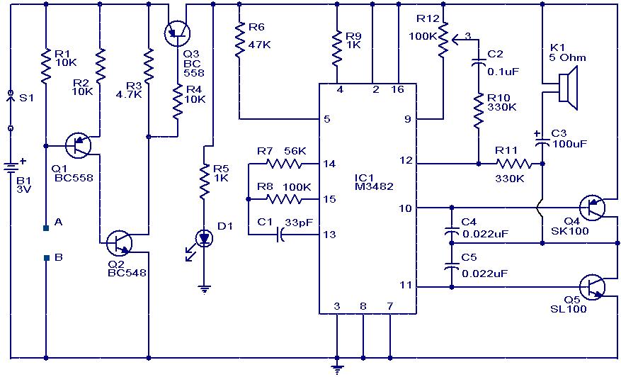
Description: This circuit is a simple musical alarm that generates a tone when water or another conductive liquid touches the two sensor wires provided. It utilizes four transistors and a melody generator integrated circuit (IC) M3482. When water bridges the sensor wires A and B, the lower terminal of Q1 connects to the negative supply, allowing current to flow. This activation turns on transistors Q2 and Q3. With Q3 in the ON state, power is supplied to the music generator circuit, which begins to produce a sequence of 12 distinct melodies. The music continues to play as long as water remains in contact with the sensor wires. A potentiometer (POT) R12 is included in the circuit as a volume control.
The musical alarm circuit operates based on the principle of conductivity detection. The two sensor wires (A and B) are strategically positioned to detect the presence of water. When a conductive liquid completes the circuit between these two points, it triggers the activation of transistor Q1. This transistor acts as a switch that connects the ground to the base of Q2 and Q3, thereby turning them ON.
Transistor Q2 serves as a current amplifier, ensuring that sufficient current flows to Q3. The role of Q3 is critical, as its activation provides the necessary power to the melody generator IC M3482. This IC is designed to produce a variety of melodies, and it is pre-programmed to cycle through 12 different tunes. The output of the IC is connected to a speaker or buzzer, which converts the electrical signals into audible sound.
The use of the potentiometer R12 allows for user-adjustable volume control, enabling the user to set the desired sound level of the alarm. This feature enhances the usability of the circuit in various environments, catering to different sound requirements.
In summary, this circuit effectively combines simple electronic components to create an engaging musical alarm system that activates in the presence of water, making it suitable for applications such as leak detection or as an alert system in wet environments. The design is straightforward, making it accessible for hobbyists and those interested in learning about basic electronics.This is a simple musical alarm circuit that produces a musical tone when water or some conducting liquid comes in contact with the 2 sensor wires provided. The circuit relies on four transistors and one melody generator IC M 3482. When water comes in contact with the sensors wires A & B, the bottom of Q1 gets connected with the negative and it con
ducts. This makes Q2 and Q3 ON. When Q3 is ON the power is offered for the music generator circuit and it starts producing 12 completely different melodies one after another. The music continues as long as there`s water between the sensor wires. The POT R12 will be used as a volume controller.
The musical alarm circuit operates based on the principle of conductivity detection. The two sensor wires (A and B) are strategically positioned to detect the presence of water. When a conductive liquid completes the circuit between these two points, it triggers the activation of transistor Q1. This transistor acts as a switch that connects the ground to the base of Q2 and Q3, thereby turning them ON.
Transistor Q2 serves as a current amplifier, ensuring that sufficient current flows to Q3. The role of Q3 is critical, as its activation provides the necessary power to the melody generator IC M3482. This IC is designed to produce a variety of melodies, and it is pre-programmed to cycle through 12 different tunes. The output of the IC is connected to a speaker or buzzer, which converts the electrical signals into audible sound.
The use of the potentiometer R12 allows for user-adjustable volume control, enabling the user to set the desired sound level of the alarm. This feature enhances the usability of the circuit in various environments, catering to different sound requirements.
In summary, this circuit effectively combines simple electronic components to create an engaging musical alarm system that activates in the presence of water, making it suitable for applications such as leak detection or as an alert system in wet environments. The design is straightforward, making it accessible for hobbyists and those interested in learning about basic electronics.This is a simple musical alarm circuit that produces a musical tone when water or some conducting liquid comes in contact with the 2 sensor wires provided. The circuit relies on four transistors and one melody generator IC M 3482. When water comes in contact with the sensors wires A & B, the bottom of Q1 gets connected with the negative and it con
ducts. This makes Q2 and Q3 ON. When Q3 is ON the power is offered for the music generator circuit and it starts producing 12 completely different melodies one after another. The music continues as long as there`s water between the sensor wires. The POT R12 will be used as a volume controller.
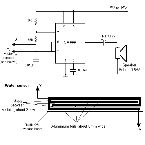
rain / water alarm circuit diagram
The sensor must be positioned at an angle of approximately 30 to 45 degrees relative to the ground. This orientation facilitates the drainage of rainwater, preventing accumulation that could trigger the alarm due to water retention on the sensor. The...
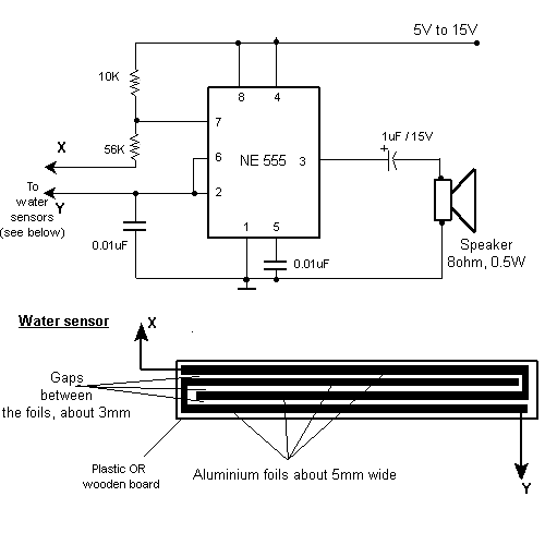
Water Alarm Circuit
This circuit activates an alarm when its sensor comes into contact with water. It employs a 555 astable multivibrator that generates a tone of approximately 1 kHz upon water detection.
The circuit consists of a 555 timer configured in astable mode,...
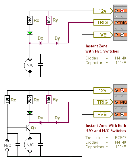
Transistor Based Burglar Alarm - Adding Extra Zones
The Transistor Burglar Alarm System allows for the addition of multiple extra zones. The primary circuit is compatible with standard normally-closed input devices, including magnetic reed contacts, micro switches, foil tape, and passive infrared sensors (PIRs). An auxiliary circuit provides...
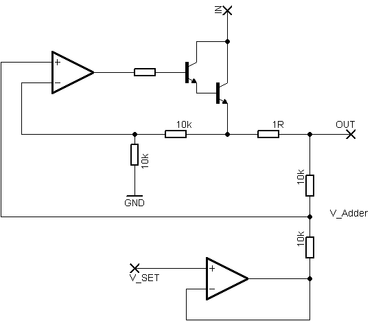
power supply Transistor current limiter microcontroller controlled
Rsense will cause Q2 to conduct when a threshold of approximately 0.65V is reached. Rbias will determine the extent of this limitation, although this aspect remains unclear. Particularly, if Rsense is positioned on the high side, simply activating Q2 with...
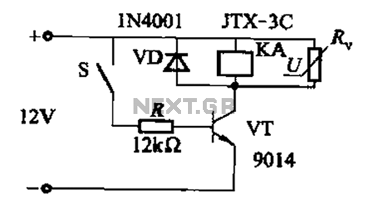
Fast response time of the control transistor circuit b
In a concrete circuit relay application, the transistor VT functions as a high-speed, high-voltage switch. The voltage requirement for switching is 5 to 10 times the rated voltage of the solenoid valve. The circuit is designed for a fast response...

Dynamic Microphone Preamplifier using C945 transistor
This circuit utilizes three transistors (2SC945, 2C1815, or 2SC828) as the primary components, functioning as a typical low-noise transistor amplifier. It offers a gain of approximately 200 to 300 times and has a frequency response ranging from 50Hz to 100KHz....

Long-Duration Time Delay
Transistor Q1 and resistors R1, R2, and R3 form a constant current source, with the charge current adjustable to as low as a few nanoamperes. This current is insufficient to activate the UJT, where IP is 0.2 A, unless a...
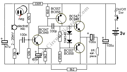
Small Amplifier Using Transistors
The output of this circuit is push-pull and consumes less than 3 mA (with no signal) but drives the earpiece to a very loud level when audio is detected.
This circuit operates in a push-pull configuration, which allows it to efficiently...

Touch-on-off-electronic-switch
Transistors Q1 and Q2 control latches Q3 and Q4 to switch on the lamp. A high resistance from touching the electrode biases Q1 or Q2 on, setting or resetting the latch.
In this circuit, transistors Q1 and Q2 function as input...