


Whistle Responder Schematic circuit
#whistle detection
#audio amplifier
#band-pass filter
#Schmitt trigger
#monostable
#astable
#beeper
#electret-microphone
#intermittent beep
#sound-activated
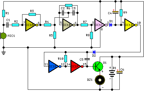
Description: This device emits intermittent beeping for approximately two seconds when a whistle is detected within a range of several meters. The first two inverters in IC1 function as audio amplifiers. IC1A consistently amplifies the signal captured by a small electret microphone, while IC1B serves as a band-pass filter, centered at around 1.8 kHz. This filter is essential for isolating the specific frequency of the whistle and preventing other frequencies from triggering the beeper unintentionally. IC1C is configured as a Schmitt trigger, which converts the incoming audio signal into a square wave. IC1D operates as a monostable multivibrator with a two-second delay, controlling the astable multivibrator formed by IC1E and IC1F. This oscillator produces a square wave at a frequency of 3 to 5 Hz, which drives transistor Q1 and buzzer BZ1, resulting in the intermittent beeping sound.
The circuit design employs an electret microphone that converts sound waves into an electrical signal. The output from the microphone is fed into the first inverter (IC1A), which amplifies the signal to a usable level. The amplified signal is then routed to the second inverter (IC1B), where it passes through a band-pass filter. This filter is crucial as it allows only the desired frequency range (approximately 1.8 kHz) to pass while attenuating other frequencies, thereby reducing false triggering caused by background noise.
The output from the band-pass filter is then processed by the Schmitt trigger (IC1C). The Schmitt trigger is designed to provide a clean digital signal by converting the analog audio signal into a square wave, which is more suitable for digital processing. This square wave is then fed into a monostable multivibrator (IC1D), which generates a pulse of a fixed duration (two seconds) in response to the detected whistle.
Following the monostable multivibrator, the circuit transitions to an astable multivibrator configuration formed by IC1E and IC1F. This configuration generates a continuous square wave output at a frequency between 3 to 5 Hz, which is used to drive the transistor (Q1). The transistor acts as a switch, controlling the current flow to the buzzer (BZ1). When the transistor is activated, the buzzer produces an intermittent sound, effectively alerting the user to the detected whistle.
In summary, this circuit effectively combines audio amplification, frequency filtering, signal conditioning, and timing functions to create a responsive and reliable whistle detection system that provides audible feedback through an intermittent beeping sound.This device beeps intermittently for about two seconds when a person in a range of around meters emits a whistle. The first two inverters contained in IC1 are used as audio amplifiers. IC1A amplifies consistently the signal picked-up by the small electret-microphone and IC1B acts as a band-pass filter, its frequency being centered at about 1.8KHz.
The filter is required in order to select a specific frequency, the whistle`s one, stopping other frequencies that would cause undesired beeper operation. IC1C is wired as a Schmitt trigger, squaring the incoming audio signal. IC1D is a 2 second-delay monostable driving the astable formed by IC1E & IC1F. This oscillator generates a 3 to 5Hz square wave feeding Q1 and BZ1, thus providing intermittent beeper operation..
The circuit design employs an electret microphone that converts sound waves into an electrical signal. The output from the microphone is fed into the first inverter (IC1A), which amplifies the signal to a usable level. The amplified signal is then routed to the second inverter (IC1B), where it passes through a band-pass filter. This filter is crucial as it allows only the desired frequency range (approximately 1.8 kHz) to pass while attenuating other frequencies, thereby reducing false triggering caused by background noise.
The output from the band-pass filter is then processed by the Schmitt trigger (IC1C). The Schmitt trigger is designed to provide a clean digital signal by converting the analog audio signal into a square wave, which is more suitable for digital processing. This square wave is then fed into a monostable multivibrator (IC1D), which generates a pulse of a fixed duration (two seconds) in response to the detected whistle.
Following the monostable multivibrator, the circuit transitions to an astable multivibrator configuration formed by IC1E and IC1F. This configuration generates a continuous square wave output at a frequency between 3 to 5 Hz, which is used to drive the transistor (Q1). The transistor acts as a switch, controlling the current flow to the buzzer (BZ1). When the transistor is activated, the buzzer produces an intermittent sound, effectively alerting the user to the detected whistle.
In summary, this circuit effectively combines audio amplification, frequency filtering, signal conditioning, and timing functions to create a responsive and reliable whistle detection system that provides audible feedback through an intermittent beeping sound.This device beeps intermittently for about two seconds when a person in a range of around meters emits a whistle. The first two inverters contained in IC1 are used as audio amplifiers. IC1A amplifies consistently the signal picked-up by the small electret-microphone and IC1B acts as a band-pass filter, its frequency being centered at about 1.8KHz.
The filter is required in order to select a specific frequency, the whistle`s one, stopping other frequencies that would cause undesired beeper operation. IC1C is wired as a Schmitt trigger, squaring the incoming audio signal. IC1D is a 2 second-delay monostable driving the astable formed by IC1E & IC1F. This oscillator generates a 3 to 5Hz square wave feeding Q1 and BZ1, thus providing intermittent beeper operation..
18W Audio Amplifier
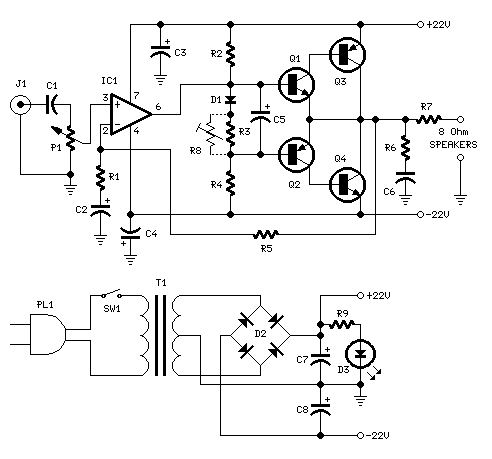
18W Audio Amplifier. High-quality, very simple unit—no need for a preamplifier. Circuit diagram: Amplifier parts: P1 = 22K Log Potentiometer.
The 18W audio amplifier is designed to deliver high-quality sound amplification in a straightforward configuration, eliminating the need for a preamplifier...
10 Watt Power Amplifier (TDA2030)
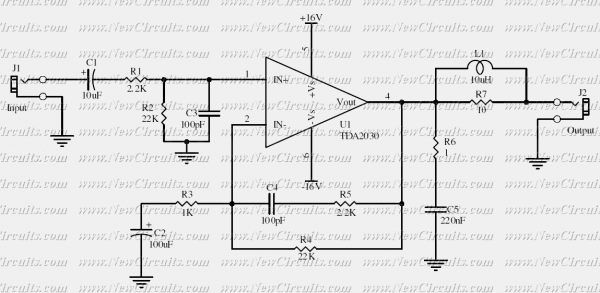
This simple 10 watts audio power amplifier is designed for home-brewed purpose. It is based on an Audio Power Amplifier IC that is called TDA2030. It is a monolithic integrated circuit in Pentawatt package, intended for use as a low...
60 Watt MosFet Audio Amplifier
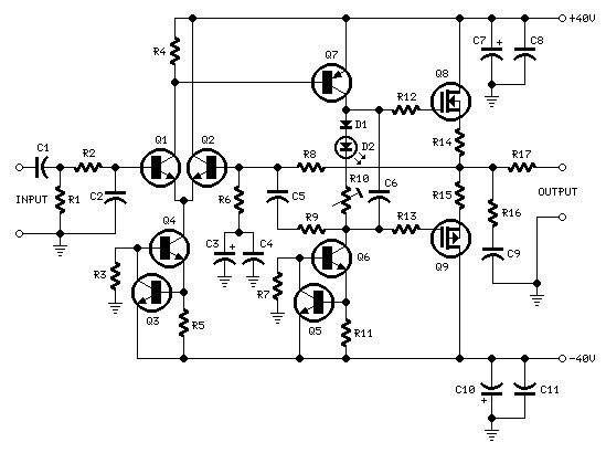
R1_47K 1/4W Resistor, R2_4K7 1/4W Resistor, R3_22K 1/4W Resistor, R4_1K 1/4W Resistor, R5, R12, R13_330R 1/4W Resistors, R6_1K5 1/4W Resistor, R7_15K 1/4W Resistor, R8_33K 1/4W Resistor, R9_150K 1/4W Resistor, R10_500R 1/2W Trimmer Cermet, R11_39R 1/4W Resistor, R14, R15_R33 2.5W Resistors,...
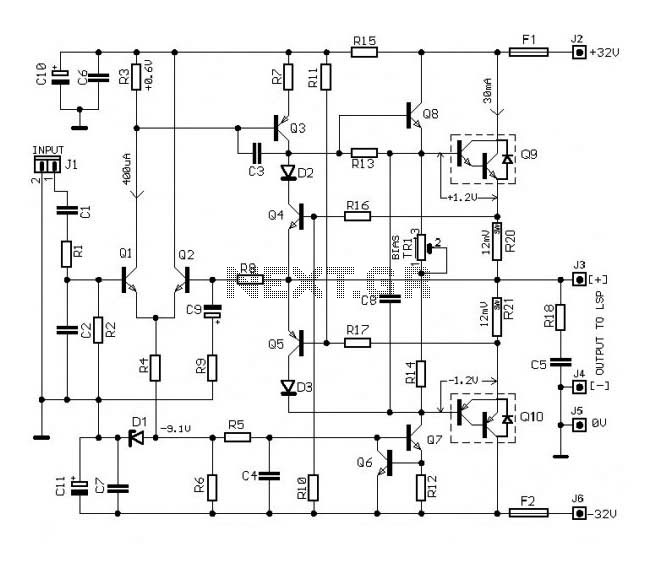
30w Audio Amplifier Circuit
The circuit of this 30W audio amplifier produces clear audio output quality. The circuit module does not have any improvements. It utilizes a Darlington pair in the transistor configuration.
The 30W audio amplifier circuit is designed to deliver high-fidelity sound reproduction,...
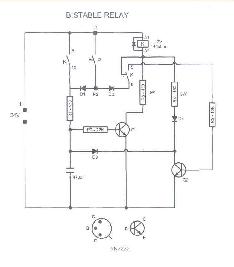
Monostable to bistable relay with momentary switch
This circuit could be used to drive a monostable relay by a single momentary switch. Powered by 24 Volts, it works for a 12 Volts relay. When the button is pressed, Q1 is energized and the capacitor charges, while the...
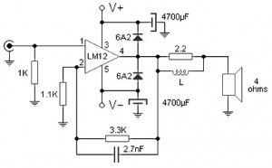
100 W audio amplifier based LM12CLK
The 100W audio power amplifier is powered by the integrated circuit LM12CLK, which is an operational power amplifier.
The 100W audio power amplifier utilizing the LM12CLK integrated circuit is designed to deliver high-quality audio output with significant power handling capabilities. The...
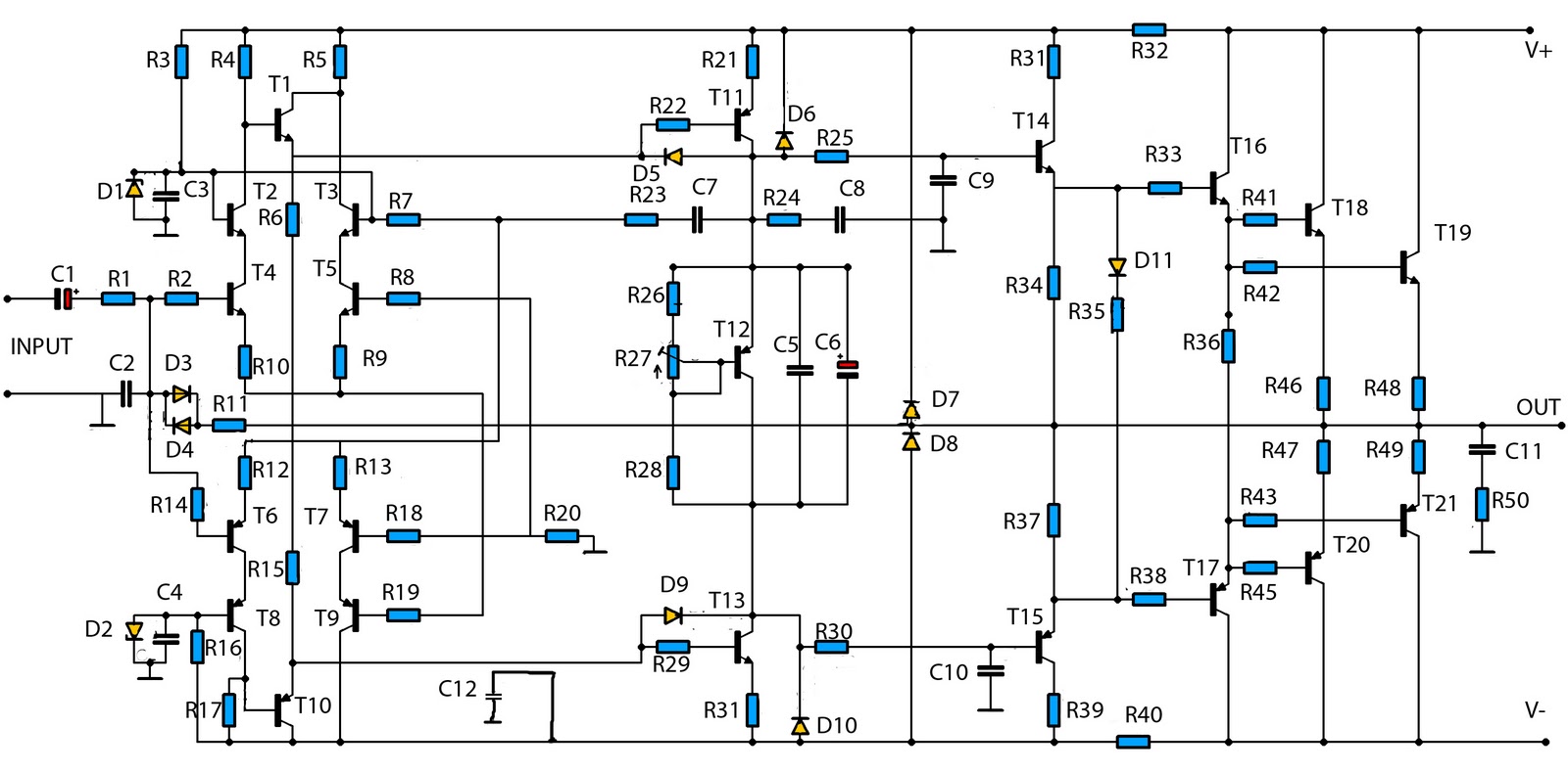
1400w audio power amplifier
This is a mono amplifier circuit with a high output power of 1400W. It is well-suited for use in large rooms with woofer and full-range speakers, delivering a loud and clear sound with minimal noise. The amplifier utilizes high-quality transistors,...
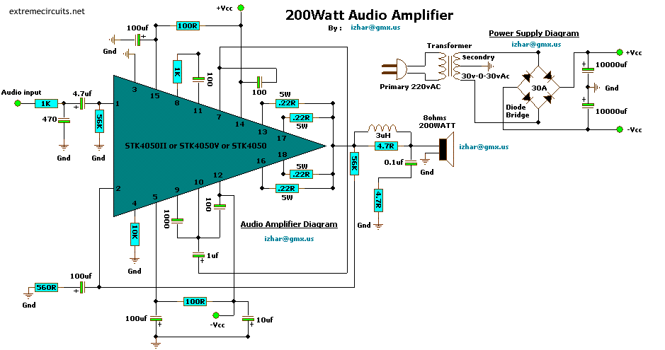
Audio Schematic Audio Amplifier Circuit 200W
This complete aerial quality, low noise address audio amplifier is based on the Hybrid Integrated Circuit STK4050 manufactured by Sanyo. The circuit incorporates all necessary components and has a maximum output power of 200W. It features an onboard power supply,...
Bull horn
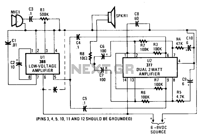
The input audio signal is connected to pin 3 of U1, an LM386 low-voltage amplifier, through capacitor C3 and resistor R1. The potentiometer R1 adjusts the drive or volume level. U1 functions as a driver stage, with a gain that...