


Zone Alarm System
#zone alarm
#exit delay
#LED indicator
#security system
#timing circuit
#arming indicator
#bell box
#visual alarm
#system armed
#delay adjustment
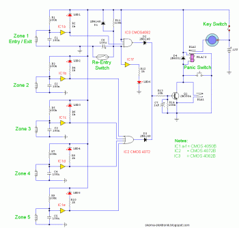
Description: Upon powering on, capacitor C6 charges through resistor R11, creating an exit delay set to approximately 30 seconds. This timing can be adjusted by changing the values of either C6 or R11. After the designated time has passed, LED6 illuminates, indicating that the system is armed. LED6 can be installed externally, such as on a bell box, to provide a visual signal that the system is active. Once armed, any contact that opens will trigger the alarm, including Zone 1. To avoid false alarms upon entering the building, a concealed re-entry switch must be activated. This switch discharges C6 and initiates the entry timer. The re-entry switch may be a hidden reed switch placed discreetly within a door frame, making it invisible to casual observation. Additionally, activating the panic switch will trigger the alarm when the system is armed. Relay contacts RLA1 are utilized for latching purposes, while RLA2 is responsible for activating the siren or buzzer.
The circuit operates on a simple delay mechanism facilitated by the charging of capacitor C6 through resistor R11. The time delay can be tailored to suit specific requirements by adjusting the capacitance of C6 or the resistance of R11, allowing for flexibility in system configuration. The illumination of LED6 serves as a critical status indicator, providing users with a clear visual cue that the alarm system is ready and operational.
The re-entry switch is a crucial component designed to enhance user convenience while maintaining security. By discharging C6, it effectively resets the timing mechanism, allowing users to enter the premises without triggering the alarm. The choice of a concealed reed switch for this function ensures that it remains discreet and secure, preventing unauthorized access while still providing a means for legitimate entry.
The panic switch adds an additional layer of security, enabling immediate activation of the alarm in emergency situations. This feature is particularly valuable in scenarios where rapid response is necessary. The relay contacts, RLA1 and RLA2, are integral to the alarm's operation; RLA1 maintains the circuit's state once the alarm is triggered, while RLA2 activates the audible alarm, alerting individuals in the vicinity of a potential security breach.
Overall, this circuit design emphasizes both user-friendly operation and robust security measures, ensuring that the alarm system functions effectively while accommodating the needs of the user.At switch on, C6 will charge via R11, this acts as the exit delay and is set to around 30 seconds. This can be altered by varying either C6 or R11. Once the timing period has elapsed, LED6 will light, meaning the system is armed. LED6 may be mounted externally (at the bell box for example) and provides visual indication that the system has set. On ce set any contact that opens will trigger the alarm, including Zone 1. To prevent triggering the alarm on entry to the building, the concealed re-entry switch must be operated. This will discharge C6 and start the entry timer. The re-entry switch could be a concealed reed switch, located anywhere in a door frame, but invisible to the eye.
The panic switch, when pressed, will trigger the alarm when set. Relay contacts RLA1 provide the latch, RLA2 operate the siren or buzzer.
The circuit operates on a simple delay mechanism facilitated by the charging of capacitor C6 through resistor R11. The time delay can be tailored to suit specific requirements by adjusting the capacitance of C6 or the resistance of R11, allowing for flexibility in system configuration. The illumination of LED6 serves as a critical status indicator, providing users with a clear visual cue that the alarm system is ready and operational.
The re-entry switch is a crucial component designed to enhance user convenience while maintaining security. By discharging C6, it effectively resets the timing mechanism, allowing users to enter the premises without triggering the alarm. The choice of a concealed reed switch for this function ensures that it remains discreet and secure, preventing unauthorized access while still providing a means for legitimate entry.
The panic switch adds an additional layer of security, enabling immediate activation of the alarm in emergency situations. This feature is particularly valuable in scenarios where rapid response is necessary. The relay contacts, RLA1 and RLA2, are integral to the alarm's operation; RLA1 maintains the circuit's state once the alarm is triggered, while RLA2 activates the audible alarm, alerting individuals in the vicinity of a potential security breach.
Overall, this circuit design emphasizes both user-friendly operation and robust security measures, ensuring that the alarm system functions effectively while accommodating the needs of the user.At switch on, C6 will charge via R11, this acts as the exit delay and is set to around 30 seconds. This can be altered by varying either C6 or R11. Once the timing period has elapsed, LED6 will light, meaning the system is armed. LED6 may be mounted externally (at the bell box for example) and provides visual indication that the system has set. On ce set any contact that opens will trigger the alarm, including Zone 1. To prevent triggering the alarm on entry to the building, the concealed re-entry switch must be operated. This will discharge C6 and start the entry timer. The re-entry switch could be a concealed reed switch, located anywhere in a door frame, but invisible to the eye.
The panic switch, when pressed, will trigger the alarm when set. Relay contacts RLA1 provide the latch, RLA2 operate the siren or buzzer.
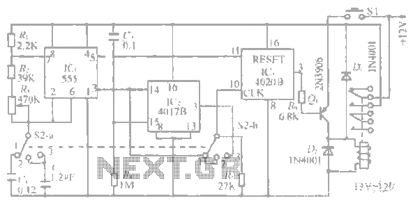
1-20 minutes a timing circuit
The system operates between 10 minutes to 2 hours, featuring a 100-line bell controlled by a multi-gear stick labeled S2 41f. The integrated circuit (IC) functions as a self-excited multivibrator. The device can manage binary pulses ranging from 3 to...
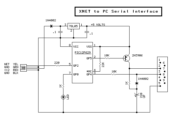
PC interfaced Security System
Creating a modular, networked, home control system was greatly simplified by using common 4-wire phone cable with stake-on connectors. The cable feeds both power and network signals to the various modules. Each module is made on a single sided circuit...
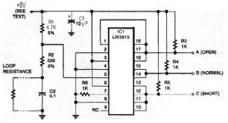
safe and security system
This security system is essential for homes, offices, and factories. It includes a circuit diagram that is simple and easy to construct, making it accessible for anyone. The circuit is cost-effective. Many security systems utilize a closed loop of wires...
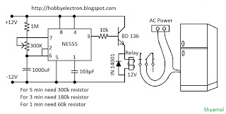
freeze protector circuit
This is a simple freeze protector circuit diagram, also known as a timing circuit. It serves as a hobby project for beginners. This circuit can automatically operate any device after a fixed time once AC power supply is restored. The...
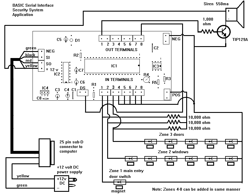
Home security system
The security system application and program offers a simple demonstration of the BASIC Serial Interface. By adding only a few door and window switches, a transistor, a siren, and a few lines of BASIC program the interface can become a...
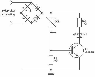
Audio Peak / Beat LED indicator
This indicator can be used, or see if your speakers can be damaged by the noise power. With P1 you can set the limit to which D1 LED lights. The pot is 100k here, you can even experiment with other...
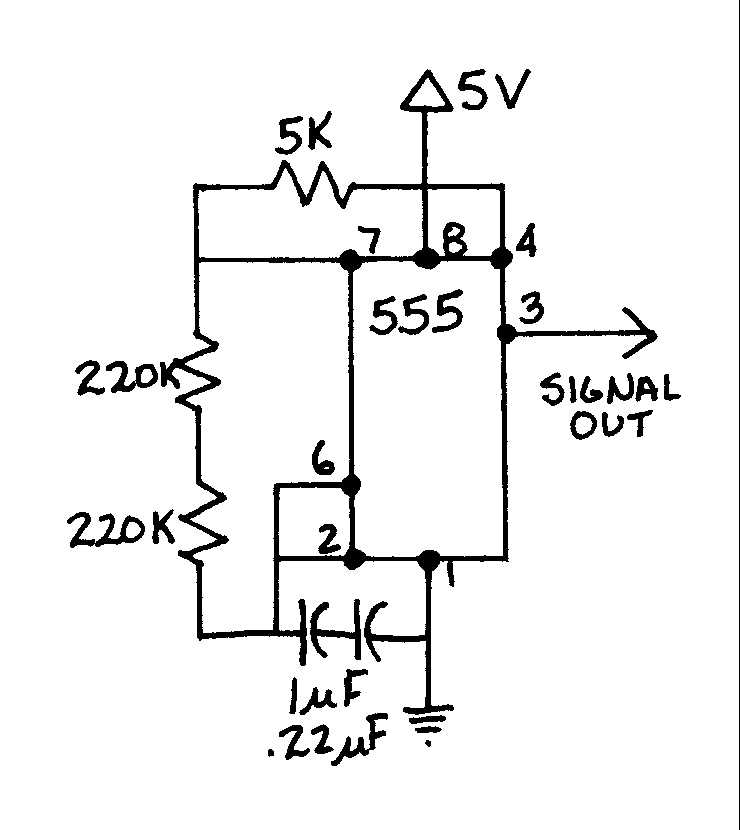
EGR 450 Manufacturing Controls Project
A timing and counting circuit utilizing integrated circuit chips with seven-segment LED displays is employed to show the current lap time, previous lap time, and total number of laps completed on a 1/64th-scale slot car racetrack. A switch activated by...
timing circuit
Assistance is needed for the design of a timing circuit intended to activate a spark plug every 10 or 20 revolutions of a shaft.
The timing circuit for firing a spark plug at specified intervals can be designed using a combination...
1-20 minutes a timing circuit
The system operates between 10 minutes to 2 hours, featuring a 100-line bell controlled by a multi-gear stick labeled S2 41f. The integrated circuit (IC) functions as a self-excited multivibrator. The device can manage binary pulses ranging from 3 to...