


16 watt amplifier
#audio amplifier
#LM383
#power amplifier
#16 watt
#heat sink
#audio circuits
#power audio
#stereo amplifier
#sound system
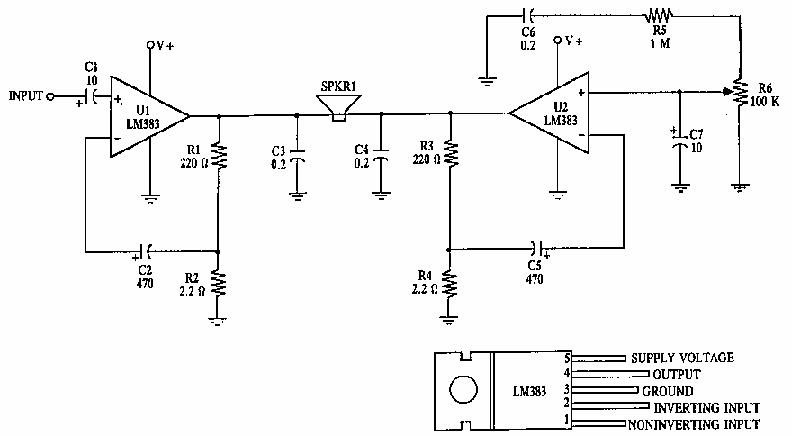
Description: This circuit provides 16 watts of amplification. It is built using two LM383 power audio amplifiers. Use suitable heat sinks with the ICs. More: U1 U2 LM383 8 watt audio amplifier IC R1, R3 220 ohm resistor R2, R4 2.2 ohm resistor R5 1 megohm resistor R6 100k audio taper potentiometer C1, C7 10uf electrolytic capacitor C2, C5 470uf electrolytic capacitor C3, C4, C6 0.2uf ceramic capacitor
The circuit is designed to deliver a total output power of 16 watts, utilizing two LM383 integrated circuits, each capable of providing 8 watts of audio amplification. The LM383 is a power audio amplifier that is known for its reliability and efficiency in audio applications.
In this configuration, U1 and U2 represent the two LM383 amplifiers, which are the heart of the circuit. Each amplifier requires proper thermal management; therefore, it is essential to attach suitable heat sinks to the ICs to prevent overheating during operation.
Resistors R1 and R3 are both 220 ohms, and they are likely used for biasing or feedback purposes within the amplifiers. Resistors R2 and R4, with a value of 2.2 ohms, may serve as current sensing or load resistors, contributing to the stability and performance of the output stage. R5, a 1 megohm resistor, is typically used in audio circuits for input impedance matching or as part of the feedback network to set the gain of the amplifier.
The circuit includes a 100k audio taper potentiometer, R6, which allows for volume control. This potentiometer is essential for user interaction, enabling the adjustment of the output level based on the desired listening volume.
Capacitors play a crucial role in audio circuits for coupling and decoupling signals. Capacitors C1 and C7 are 10 µF electrolytic capacitors, which may be used for coupling the audio signal to the amplifiers, ensuring that only the AC component of the audio signal passes while blocking any DC offset. Capacitors C2 and C5, rated at 470 µF, are likely used for power supply decoupling, providing stability and filtering against voltage fluctuations. Finally, C3, C4, and C6 are 0.2 µF ceramic capacitors, which may be employed for high-frequency bypassing, ensuring that high-frequency noise does not affect the performance of the amplifiers.
The overall design emphasizes audio fidelity and stability, suitable for various audio amplification applications. Proper layout and component selection are critical to achieving the desired performance and reliability in the final circuit implementation.This circuit provides 16 watts of amplification. it is built using two LM383 power audio amplifiers. use suitable heat sinks with the ic`s. U1 U2 LM383 8 watt audio amplifier ic R1, R3 220 ohm resistor R2, R4 2.2 ohm resistor R5 1 megohm resistor R6 100k audio taper potentiometer C1, C7 10uf electrolytic capacitor C2, C5 470uf electrolytic capacitor C3, C4, C6 0.2uf ceramic capacitor
The circuit is designed to deliver a total output power of 16 watts, utilizing two LM383 integrated circuits, each capable of providing 8 watts of audio amplification. The LM383 is a power audio amplifier that is known for its reliability and efficiency in audio applications.
In this configuration, U1 and U2 represent the two LM383 amplifiers, which are the heart of the circuit. Each amplifier requires proper thermal management; therefore, it is essential to attach suitable heat sinks to the ICs to prevent overheating during operation.
Resistors R1 and R3 are both 220 ohms, and they are likely used for biasing or feedback purposes within the amplifiers. Resistors R2 and R4, with a value of 2.2 ohms, may serve as current sensing or load resistors, contributing to the stability and performance of the output stage. R5, a 1 megohm resistor, is typically used in audio circuits for input impedance matching or as part of the feedback network to set the gain of the amplifier.
The circuit includes a 100k audio taper potentiometer, R6, which allows for volume control. This potentiometer is essential for user interaction, enabling the adjustment of the output level based on the desired listening volume.
Capacitors play a crucial role in audio circuits for coupling and decoupling signals. Capacitors C1 and C7 are 10 µF electrolytic capacitors, which may be used for coupling the audio signal to the amplifiers, ensuring that only the AC component of the audio signal passes while blocking any DC offset. Capacitors C2 and C5, rated at 470 µF, are likely used for power supply decoupling, providing stability and filtering against voltage fluctuations. Finally, C3, C4, and C6 are 0.2 µF ceramic capacitors, which may be employed for high-frequency bypassing, ensuring that high-frequency noise does not affect the performance of the amplifiers.
The overall design emphasizes audio fidelity and stability, suitable for various audio amplification applications. Proper layout and component selection are critical to achieving the desired performance and reliability in the final circuit implementation.This circuit provides 16 watts of amplification. it is built using two LM383 power audio amplifiers. use suitable heat sinks with the ic`s. U1 U2 LM383 8 watt audio amplifier ic R1, R3 220 ohm resistor R2, R4 2.2 ohm resistor R5 1 megohm resistor R6 100k audio taper potentiometer C1, C7 10uf electrolytic capacitor C2, C5 470uf electrolytic capacitor C3, C4, C6 0.2uf ceramic capacitor
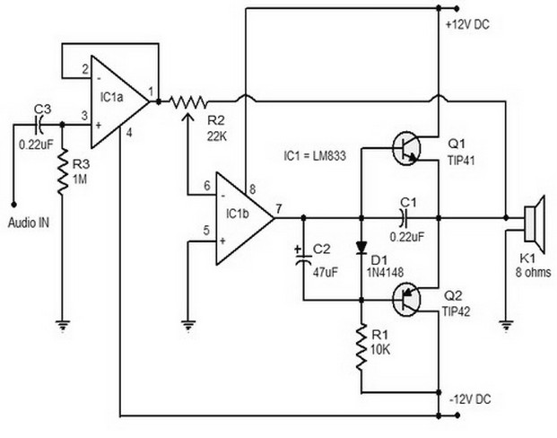
15w class b audio amplifie0r
The 15W Class B audio amplifier circuit presented here is a straightforward Class B audio amplifier utilizing the TL082 operational amplifier, along with TIP41 and TIP42 transistors. The LM833 is a dual amplifier known for its high scanning speed and...
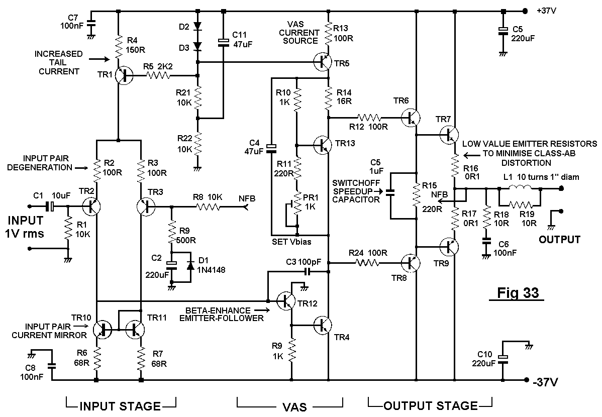
Distortion In Power Amplifiers
The distortion produced by a typical solid-state Class-B power amplifier consists of eight mechanisms, all of which may coexist and whose distortion products overlap to create a complex result. Methods for isolating each mechanism for study and minimizing its contribution...
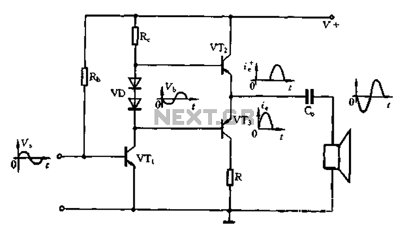
Complementary symmetry push-pull circuit
The Class A power amplifier exhibits low distortion; however, it suffers from low efficiency and limited output power, prompting the design of Class B power amplifier circuits. The Class B amplifier operates by shifting the operating point of the transistor...
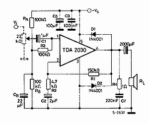
Circuit of power audio amplifier with circuit integrated tda2030 car amplifier 14 watts rms
The TDA2030 is a monolithic integrated circuit in a Pentawat® package designed to function as a Class AB audio amplifier. It typically delivers up to 14 watts of output power (with a distortion rate of 0.5%) at 14V with a...
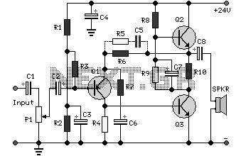
5 watt class a audio amplifier circuit
This solid-state push-pull single-ended Class A circuit is capable of providing sound quality comparable to that of valve amplifiers. It delivers an output power of 6.9W when measured across an 8 Ohm loudspeaker cabinet load, with reduced total harmonic distortion...
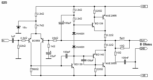
60 Watt Into 8 Ohms Power Amplifier
Cleaned Input: This amplifier does not claim to be state of the art, and in fact the base design is now over 20 years old. It is a simple amp to build, uses commonly available parts and is stable and...
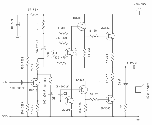
60W Power Amplifier with 2N3055
Simple and low cost. The optimal supply voltage is around 50V, but this amp works from 30 to 60V. The maximal input voltage is around 0.8 - 1V. As you can see, in this design the components have a big...
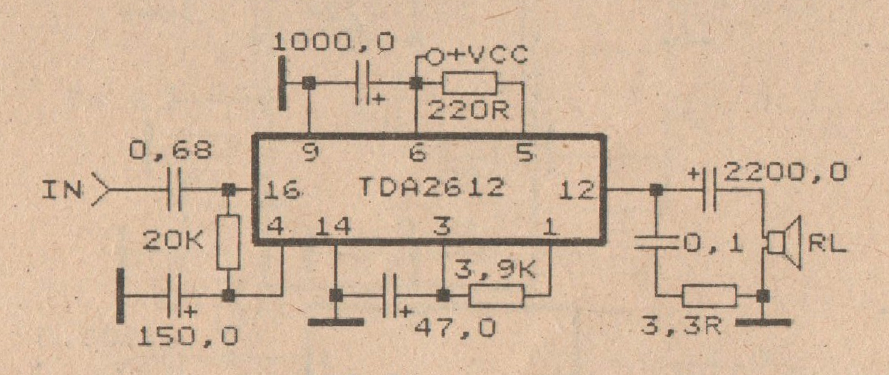
Schematic Audio Power Amplifier with IC TDA2612 Schematic Diagram
This amplifier circuit is based on the IC TDA2612 produced by Siemens. The minimum voltage required for this circuit is 10 volts, while the maximum voltage is 35 volts DC. The power output is 25 watts with a 4-ohm impedance....
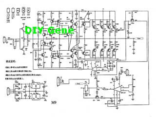
Complete Solid state M-9 Power Amplifier
The following circuit illustrates a complete solid-state M-9 power amplifier circuit diagram. Features include a DC servo that acts as a loudspeaker protection circuit.
The solid-state M-9 power amplifier circuit is designed to deliver high-quality audio amplification while ensuring the safety...