


18 dB LT1253 DDS Amplifier
#LT1253
#DDS
#video amplifier
#AD9850
#gain-bandwidth
#dual amplifier
#Manhattan-style
#high gain
#Linear Technology
#Analog Devices
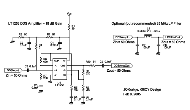
Description: This 18 dB gain amplifier was constructed using the Manhattan-style technique to assess the Linear Technology LT1253 dual video amplifier as a potential output amplifier for Direct Digital Synthesis (DDS) systems that utilize the Analog Devices AD9850 and similar devices. The dual amplifier was selected for its high gain-bandwidth product, enabling the creation of a broadband system with a frequency range from 100 KHz to over 30 MHz. The amplifier schematic is designed with 50 Ohm input and output impedances and provides slightly more than 18 dB of power gain. The LT1253 comprises two current feedback amplifier sections, with the voltage gain calculated using the formula: A = 1 + Rf/Rg, where Rf is a 620 Ohm resistor and Rg is a 200 Ohm resistor. Each amplifier section operates at a voltage gain of 4. The constructed amplifier features a BNC connector for input on the left and another for output on the right. It can be powered by a supply voltage ranging from 8 to 14 volts with minimal performance variation. An optional low-pass filter is indicated in the schematic; however, this additional circuitry was neither built nor tested. A frequency response plot of the LT1253 DDS amplifier shows minimal amplitude variation (approximately 0.5 dB) from 1 MHz to 30 MHz. The amplifier remains effective up to 40 MHz in its current configuration, and with slight adjustments to the overall gain (specifically lowering it), it may be capable of functioning up to 50 MHz, making it suitable for use at 6 meters.
The amplifier circuit utilizes the LT1253, which is a high-performance dual video amplifier known for its low distortion and high bandwidth capabilities. The design employs a current feedback topology that enhances stability and allows for higher bandwidth operation compared to traditional voltage feedback amplifiers. The choice of 50 Ohm impedance is critical for matching with typical RF applications, ensuring maximum power transfer and minimizing reflections in the circuit.
The gain configuration is achieved through the resistor network formed by Rf and Rg. The selected resistor values provide a voltage gain of 4 for each amplifier section, resulting in a total gain of approximately 18 dB when both sections are utilized in tandem. The use of high-quality components in the feedback loop is essential for maintaining the integrity of the signal across the specified frequency range.
The BNC connectors facilitate easy integration into existing systems, allowing for straightforward testing and measurement. The power supply requirements of 8 to 14 volts provide flexibility in powering the amplifier, accommodating various applications without significant changes in performance characteristics.
The optional low-pass filter, while not implemented in this version of the amplifier, could be integrated into future designs to further refine the output signal by attenuating unwanted high-frequency noise. The frequency response characteristics indicate that the amplifier is well-suited for applications requiring stable gain across a wide frequency range, making it an ideal choice for DDS systems and other RF applications. The potential to extend the operational bandwidth to 50 MHz enhances its versatility, particularly for use in amateur radio or other high-frequency communication systems.This 18 dB gain amplifier was built Manhattan-style to evaluate the Linear Technology LT1253 dual video amplifier as a candidate output amplifier for DDS systems employing the Analog Devices AD9850 and similar devices. This dual amplifier was chosen to take advantage of its high gain-bandwidth product. By utilizing both amplifier sections, a very broadband (100 KHz to 30+ MHz), high gain system could be built. The amplifier schematic is shown above. It is configured to have 50 Ohm input and output impedances, and a bit over 18 dB of power gain. The LT1253 contains two current feedback amplifier sections. The voltage gain is given by the equation: A = 1 + Rf/Rg where Rf is a 620 Ohm resistor and Rg a 200 Ohm resistor. Each amplifier section is running at a voltage gain of 4. 1. Here is the amplifier that was constructed and tested. The BNC connector on the left is the input, and the one on the right is the output. The amplifier can be powered using a supply of 8 to 14 volts with little change in performance. An optional low pass filter is shown in the schematic, but that circuitry was neither constructed nor tested.
A Bode or frequency response plot of the LT1253 DDS amplifier. Note there is very little change in amplitude (about 1/2 dB) from 1 MHz to 30 MHz. In fact, the amplifier is quite useable out to 40 MHz as configured. With small changes in overall gain (lower), it could probably be pushed to 50 MHz, allowing it to be used at 6 meters.
The amplifier circuit utilizes the LT1253, which is a high-performance dual video amplifier known for its low distortion and high bandwidth capabilities. The design employs a current feedback topology that enhances stability and allows for higher bandwidth operation compared to traditional voltage feedback amplifiers. The choice of 50 Ohm impedance is critical for matching with typical RF applications, ensuring maximum power transfer and minimizing reflections in the circuit.
The gain configuration is achieved through the resistor network formed by Rf and Rg. The selected resistor values provide a voltage gain of 4 for each amplifier section, resulting in a total gain of approximately 18 dB when both sections are utilized in tandem. The use of high-quality components in the feedback loop is essential for maintaining the integrity of the signal across the specified frequency range.
The BNC connectors facilitate easy integration into existing systems, allowing for straightforward testing and measurement. The power supply requirements of 8 to 14 volts provide flexibility in powering the amplifier, accommodating various applications without significant changes in performance characteristics.
The optional low-pass filter, while not implemented in this version of the amplifier, could be integrated into future designs to further refine the output signal by attenuating unwanted high-frequency noise. The frequency response characteristics indicate that the amplifier is well-suited for applications requiring stable gain across a wide frequency range, making it an ideal choice for DDS systems and other RF applications. The potential to extend the operational bandwidth to 50 MHz enhances its versatility, particularly for use in amateur radio or other high-frequency communication systems.This 18 dB gain amplifier was built Manhattan-style to evaluate the Linear Technology LT1253 dual video amplifier as a candidate output amplifier for DDS systems employing the Analog Devices AD9850 and similar devices. This dual amplifier was chosen to take advantage of its high gain-bandwidth product. By utilizing both amplifier sections, a very broadband (100 KHz to 30+ MHz), high gain system could be built. The amplifier schematic is shown above. It is configured to have 50 Ohm input and output impedances, and a bit over 18 dB of power gain. The LT1253 contains two current feedback amplifier sections. The voltage gain is given by the equation: A = 1 + Rf/Rg where Rf is a 620 Ohm resistor and Rg a 200 Ohm resistor. Each amplifier section is running at a voltage gain of 4. 1. Here is the amplifier that was constructed and tested. The BNC connector on the left is the input, and the one on the right is the output. The amplifier can be powered using a supply of 8 to 14 volts with little change in performance. An optional low pass filter is shown in the schematic, but that circuitry was neither constructed nor tested.
A Bode or frequency response plot of the LT1253 DDS amplifier. Note there is very little change in amplitude (about 1/2 dB) from 1 MHz to 30 MHz. In fact, the amplifier is quite useable out to 40 MHz as configured. With small changes in overall gain (lower), it could probably be pushed to 50 MHz, allowing it to be used at 6 meters.
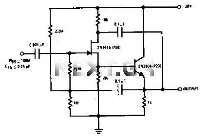
High gain amplifier circuit
The 2N5485, which has a very low-capacity legacy, is always operated as a source follower with gate bias bootstrap. In this circuit, nothing is left to chance in reducing input capacitance.
The 2N5485 is a JFET (Junction Field Effect Transistor) known...
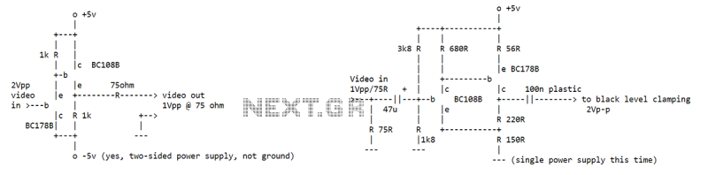
Video amplifier
I've seen an NE592 used as a video buffer amp at the end of a 75 ohm line. Used so that the 75 ohm line could drive all kinds of neat processing stuff without affecting the signal (that's what a...

Direct Digital Synthesis Oscillator
The AD9835 combines the Numerical Controlled Oscillator (NCO), COS Look-Up Table, Frequency and Phase Modulators, and a Digital-to-Analog Converter on a single integrated circuit. With more easy words you can say that this circuit is an oscillator where the frequency...
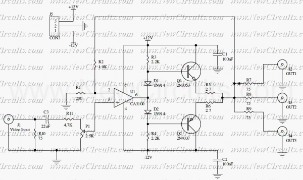
Video Distributor Amplifier CA3100
This circuit is useful to amplify and distribute video signals with low noise and without losses. The CA3100 is a fast opamp designed to amplify video signals. Set the P1 to control the input signal level to have a clear...
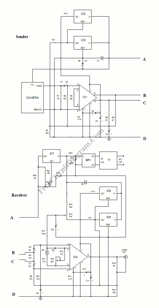
Video Wire: Enable Video Transmission Via Long Cables
This circuit allows for the connection of a camera using a very long wire. The circuit functions as a video amplifier. At the sending end, the amplifier is utilized to.
The circuit described is designed to facilitate the transmission of video...
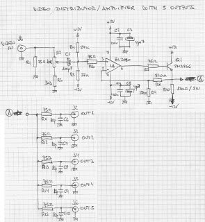
video distibution amplifier with five
The circuit presented here has numerous applications. Essentially, the distribution amplifier receives a composite video signal from a video player (VCR) or a video generator (analog output) and buffers it, allowing it to be simultaneously sent to up to five...
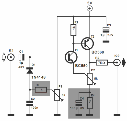
Video Amplifier
The video amplifier illustrated in the diagram represents a well-established design that is simple yet highly effective. However, there is a risk of damaging the transistors if the potentiometers, which control black level and signal amplitude, are set to their...
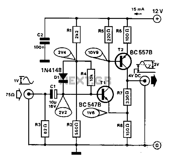
Simple video amplifier circuit diagram
Commonly used for cameras or computers with black and white television connections, the amplifier has a gain of 3 and a bandwidth of 10 MHz.
The described circuit is an amplifier designed for applications involving cameras or computers that interface with...
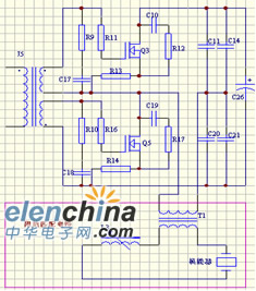
DDS-based automatic tracking frequency ultrasonic generator
Ultrasonic cleaning primarily relies on the phenomenon of ultrasonic cavitation. In the presence of a sound field, liquid bubbles undergo high-frequency micro-vibrations. When the sound pressure reaches a specific threshold, air bubbles grow rapidly and then collapse suddenly, creating a...