


25W Class-A Hi-Fi Power Amplifier
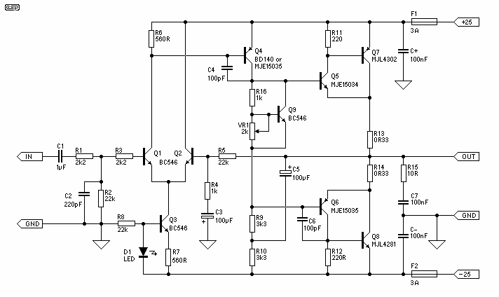
The basis for this amplifier has been around now for several years as Project 3A, and requires only relatively small modifications to be able to operate in Class-A. The biggest change is in output power (reduced dramatically from the 60-100W of the Class-AB version), but at 25W is still more than enough for many people.
The amplifier, known as Project 3A, has been designed to operate in Class-A mode with only minor adjustments necessary. Class-A amplifiers are characterized by their output devices always being active, regardless of the output signal amplitude. This leads to a very linear output but with lower efficiency compared to other classes of amplifiers.
The most significant alteration in this version of the amplifier is the reduction in output power. Originally, the Class-AB version of this amplifier could produce between 60-100W. However, in the Class-A version, this has been dramatically decreased to 25W. Despite this reduction, 25W is still a considerable amount of power and is more than sufficient for many users' needs.
The output power of an amplifier is a critical factor as it determines the maximum volume that can be achieved. However, it's worth noting that doubling the power does not double the volume. Therefore, while the output power of this Class-A version is significantly less than its Class-AB counterpart, the difference in perceived volume may not be as substantial as the numbers suggest.
This amplifier, therefore, represents a balance between performance and power consumption. While it may not deliver the same power as its Class-AB version, it provides a more linear output, which can result in a cleaner, more accurate sound reproduction. This makes it an ideal choice for audiophiles and those who prioritize sound quality over volume.The basis for this amplifier has been around now for several years as Project 3A, and requires only relatively small modifications to be able to operate in Class-A. The biggest change is in output power (reduced dramatically from the 60-100W of the Class-AB version), but at 25W is still more than enough for many people.
The amplifier, known as Project 3A, has been designed to operate in Class-A mode with only minor adjustments necessary. Class-A amplifiers are characterized by their output devices always being active, regardless of the output signal amplitude. This leads to a very linear output but with lower efficiency compared to other classes of amplifiers.
The most significant alteration in this version of the amplifier is the reduction in output power. Originally, the Class-AB version of this amplifier could produce between 60-100W. However, in the Class-A version, this has been dramatically decreased to 25W. Despite this reduction, 25W is still a considerable amount of power and is more than sufficient for many users' needs.
The output power of an amplifier is a critical factor as it determines the maximum volume that can be achieved. However, it's worth noting that doubling the power does not double the volume. Therefore, while the output power of this Class-A version is significantly less than its Class-AB counterpart, the difference in perceived volume may not be as substantial as the numbers suggest.
This amplifier, therefore, represents a balance between performance and power consumption. While it may not deliver the same power as its Class-AB version, it provides a more linear output, which can result in a cleaner, more accurate sound reproduction. This makes it an ideal choice for audiophiles and those who prioritize sound quality over volume.The basis for this amplifier has been around now for several years as Project 3A, and requires only relatively small modifications to be able to operate in Class-A. The biggest change is in output power (reduced dramatically from the 60-100W of the Class-AB version), but at 25W is still more than enough for many people.
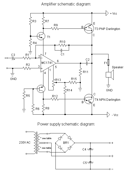
Hi-Fi power amplifier with MJ3001 and MJ2501
This is a very simple, low cost, Hi-Fi quality power amplifier. You can build it 5 ways, like it is shown in the table (from 20 W to 80 W RMS). The first thing that you must do, is to...
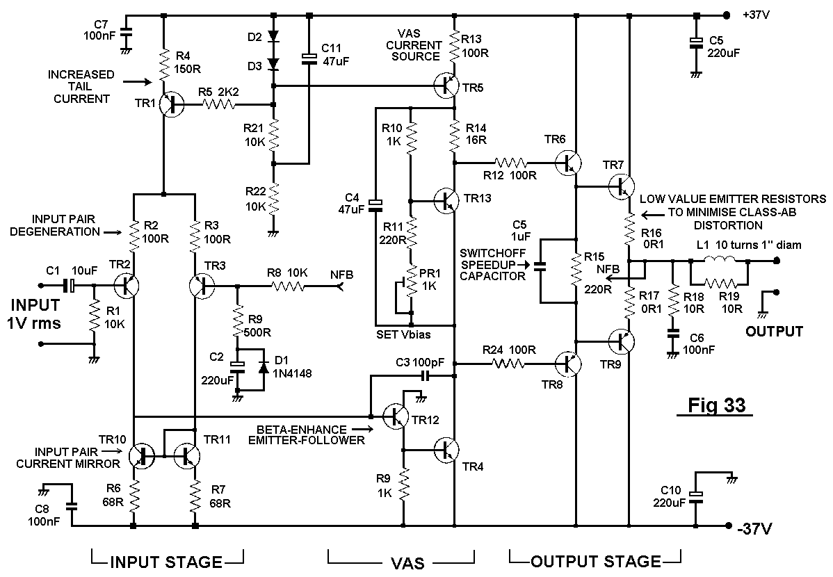
Distortion In Power Amplifiers
The distortion produced by a typical solid-state Class-B power amplifier consists of eight mechanisms, all of which may coexist and whose distortion products overlap to create a complex result. Methods for isolating each mechanism for study and minimizing its contribution...
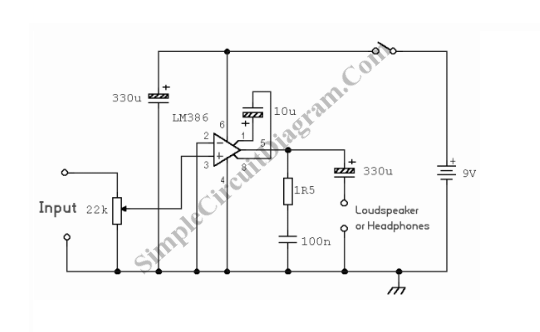
Small High Quality Audio Power Amplifier
This audio power amplifier is highly suitable for portable devices or as a headphone amplifier. The circuit design of this audio power amplifier is straightforward.
This audio power amplifier circuit is designed to enhance audio signals for portable devices and headphones,...
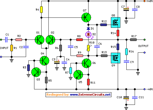
60 Watt Audio Power Amplifier
In the original circuit, a series of three diodes was connected to resistor R10. Two of these diodes have been replaced with a red LED to enhance quiescent current stability across a broader temperature range. This modification was suggested by...
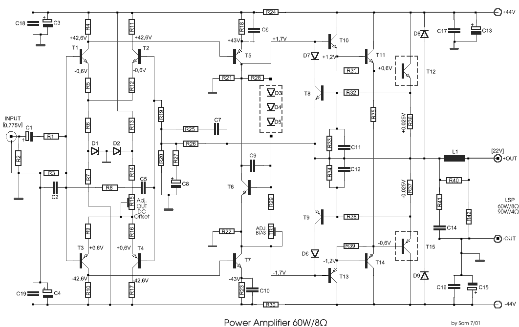
power amplifier 60w
This circuit was designed and manufactured in the 1980s. Since then, it has operated without issues. There are no specific construction challenges, aside from the usual considerations: attention to the power supply requirements, selection of an appropriate heatsink, and proper...
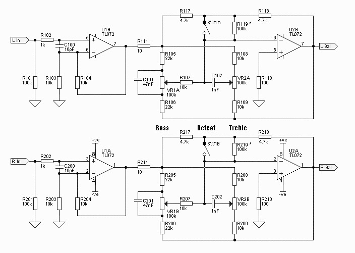
hi-fi audio amplifiers with tl072
The sound system features a de-sensitized design with a maximum range that can be increased if desired. It includes two tone controls: one offering a lift of 10 dB and the other providing a subtle cut of 3 dB. This...
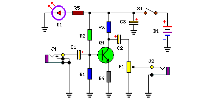
Audio Booster circuit
The amplifier's gain is nominally 20 dB. Its frequency response is primarily influenced by the values of a few components, mainly C1 and R1. The schematic diagram's component values yield a frequency response of ±3.0 dB from approximately 120 Hz...
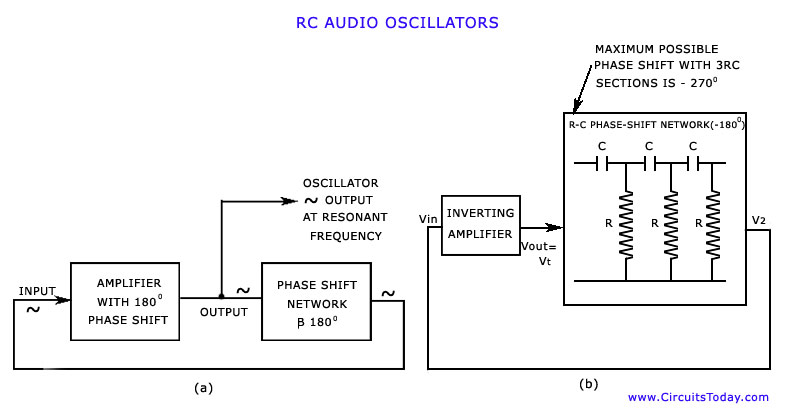
Audio Oscillators
The discussion has focused on oscillators that utilize L-C tuned circuits, which create a 180° phase shift due to inductive or capacitive coupling, in addition to another 180° phase shift produced by the transistor itself. These L-C oscillators are widely...
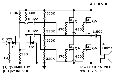
Complementary Power Amplifiers
The first schematic is designed for individuals who exclusively purchase electronic components from Radio Shack. It allows for a straightforward shopping experience, enabling one to acquire all necessary parts in-store. For the heat sink, it is recommended to visit a...