


2X15 Watt stereo amplifier using TDA4935
#TDA4935
#stereo amplifier
#audio amplifier
#bipolar IC
#overload protection
#temperature shutdown
#15W amplifier
#BTL amplifier
#mono amplifier
#power amplifier
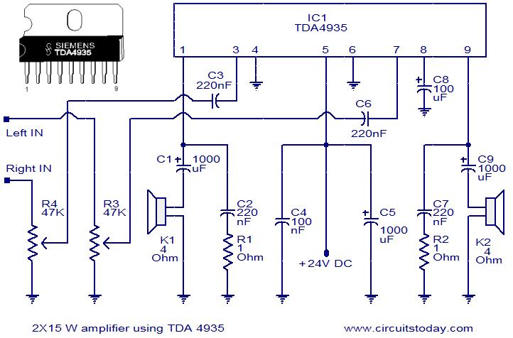
Description: The TDA4935 is a bipolar stereo amplifier integrated circuit (IC) that can be configured as either a 2x15W stereo amplifier or a 30W mono BTL (Bridge-Tied Load) amplifier. This IC includes built-in circuitry for overload protection and over-temperature shutdown. In this configuration, the IC is set up in stereo mode to deliver 15W of power to each speaker. The circuit operates without the need for a dual power supply and can be powered by a voltage range of 8V to 24V. For maximum output power, a 24V supply is utilized. According to the manufacturer's datasheet, at 20V DC, the output will be 11 watts into a 4-ohm load, achieving an efficiency of 70%. Therefore, the power input required for the chip is approximately 16 watts, which translates to a current draw of 800mA for both channels combined, resulting in a total of 1.6A. A transformer rated at 20V and 2A is recommended for optimal performance.
The TDA4935 amplifier IC is designed for efficient audio amplification in various applications, including home audio systems and portable devices. The device's ability to operate in both stereo and mono configurations allows for versatile use cases, depending on the user's requirements. In stereo mode, the amplifier provides 15W output per channel, suitable for driving standard speakers in a typical listening environment. The BTL configuration maximizes power output, making it ideal for situations where space is limited, and higher power is needed.
The built-in overload protection and over-temperature shutdown features are critical for ensuring the longevity and reliability of the amplifier. These safety mechanisms prevent damage to the IC and connected components during prolonged operation or under heavy load conditions. The flexibility of the power supply requirements, ranging from 8V to 24V, allows for easy integration into various power supply designs, making the TDA4935 suitable for both battery-operated and mains-powered applications.
When designing the circuit, it is essential to consider the output load impedance. The TDA4935 is optimized for 4-ohm speakers, which is a common impedance for many consumer audio devices. The efficiency rating of 70% indicates that a significant portion of the input power is converted to useful audio output, minimizing wasted energy as heat.
For power supply design, a transformer rated at 20V and 2A is recommended to provide sufficient headroom for the amplifier's operation. This specification ensures that the amplifier can deliver its rated output without distortion or clipping under typical load conditions. Additionally, proper filtering and decoupling capacitors should be included in the power supply circuit to maintain stable voltage levels and reduce noise, further enhancing audio quality.
Overall, the TDA4935 amplifier IC presents a robust solution for audio amplification, combining power, efficiency, and protection features in a single package.TDA4935 is bipolar stereo amplifier IC that can be wired as a 2X15W stereo amplifier or a 30W mono BTL amplifier. The IC also features built in circuitry for over load protection and over temperature shut down. Here the IC is wired in stereo mode in order to deliver 15W power on each speaker. The circuit does not require a dual power supply and it can be powered from anything between 8 to 24V. Here I am using 24V for getting maximum output power. Hi Sicko With 20 volt DC the output will be 11watts into 4 ohms as per mfg datasheet, at an efficiency of 70%. Hence the power input required for the chip is around 16watts 16/20 is 800mA both channel put together 1.
6Amps. with head room 20volt 2amp transformer is the best choice.
The TDA4935 amplifier IC is designed for efficient audio amplification in various applications, including home audio systems and portable devices. The device's ability to operate in both stereo and mono configurations allows for versatile use cases, depending on the user's requirements. In stereo mode, the amplifier provides 15W output per channel, suitable for driving standard speakers in a typical listening environment. The BTL configuration maximizes power output, making it ideal for situations where space is limited, and higher power is needed.
The built-in overload protection and over-temperature shutdown features are critical for ensuring the longevity and reliability of the amplifier. These safety mechanisms prevent damage to the IC and connected components during prolonged operation or under heavy load conditions. The flexibility of the power supply requirements, ranging from 8V to 24V, allows for easy integration into various power supply designs, making the TDA4935 suitable for both battery-operated and mains-powered applications.
When designing the circuit, it is essential to consider the output load impedance. The TDA4935 is optimized for 4-ohm speakers, which is a common impedance for many consumer audio devices. The efficiency rating of 70% indicates that a significant portion of the input power is converted to useful audio output, minimizing wasted energy as heat.
For power supply design, a transformer rated at 20V and 2A is recommended to provide sufficient headroom for the amplifier's operation. This specification ensures that the amplifier can deliver its rated output without distortion or clipping under typical load conditions. Additionally, proper filtering and decoupling capacitors should be included in the power supply circuit to maintain stable voltage levels and reduce noise, further enhancing audio quality.
Overall, the TDA4935 amplifier IC presents a robust solution for audio amplification, combining power, efficiency, and protection features in a single package.TDA4935 is bipolar stereo amplifier IC that can be wired as a 2X15W stereo amplifier or a 30W mono BTL amplifier. The IC also features built in circuitry for over load protection and over temperature shut down. Here the IC is wired in stereo mode in order to deliver 15W power on each speaker. The circuit does not require a dual power supply and it can be powered from anything between 8 to 24V. Here I am using 24V for getting maximum output power. Hi Sicko With 20 volt DC the output will be 11watts into 4 ohms as per mfg datasheet, at an efficiency of 70%. Hence the power input required for the chip is around 16watts 16/20 is 800mA both channel put together 1.
6Amps. with head room 20volt 2amp transformer is the best choice.
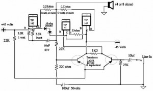
150W Power Amplifier
A 150W power amplifier circuit diagram utilizing power transistors TIP41, TIP142, and TIP147. The design is straightforward enough to construct without a printed circuit board (PCB). The power output range is approximately 100-150W.
The 150W power amplifier circuit is designed to...
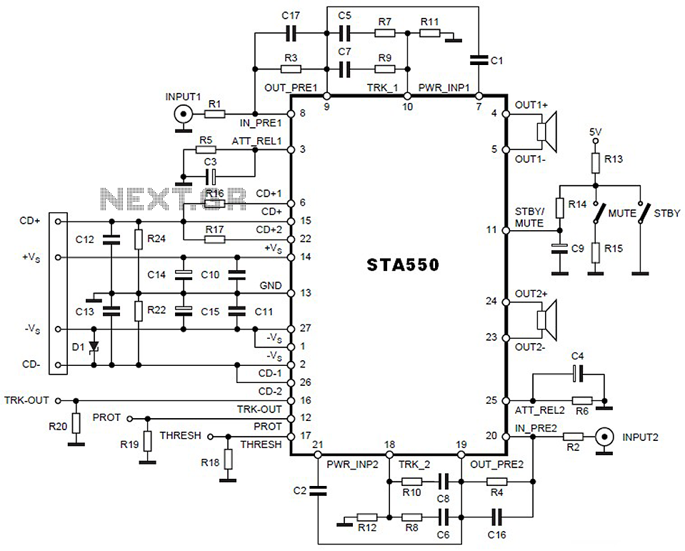
STA550 - 2 x 70W Audio Amplifier Circuit
This is a 2 x 70W audio power amplifier circuit built using a single IC STA550. The amplifier circuit requires a few external components, primarily resistors and capacitors, and is straightforward to design. The STA550 audio amplifier can provide a...
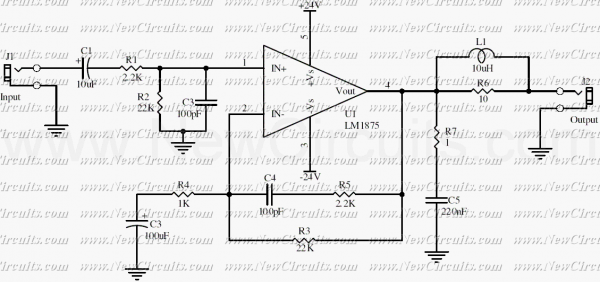
20 Watt Audio Amplifier
This simple 20 watts audio power amplifier is designed for home-brewed purpose. The L1 should be able to handle a current up to 4A to drive speaker in full load. The distortion is 0.015% @ 1KHz / 20W. This circuit...
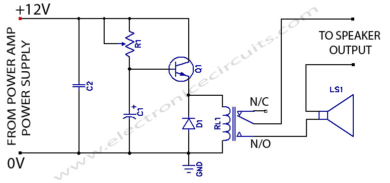
power amplifier speaker protection
When powering on a power amplifier, a loud thump sound occurs due to a sudden heavy discharge current through the speaker. This current has the potential to damage the speaker, particularly in the case of a direct-coupled amplifier.
The phenomenon described...
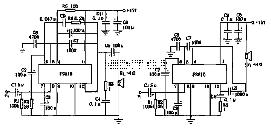
FS810 integrated power amplifier circuit diagram
The FS810 circuit serves as a practical implementation of an integrated power amplifier. The FS810 is designed for high-performance use in high-end tape recorders and audio equipment. In the schematic, the speaker is connected to the output capacitor C5 and...
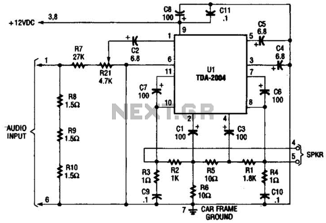
Booster Amplifier For Car Stereo Use Circuit
Only one channel of this circuit is shown. The other is practically identical. The input to the circuit, taken from the speaker output of a car radio, is divided into two paths. In one path, a high-power divider network (comprising...
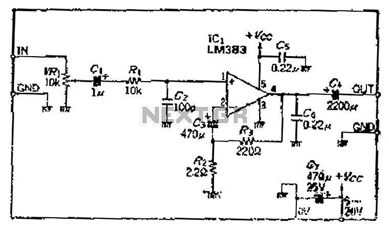
The use of monolithic power IC 6 to W audio power amplifier
A closed-loop amplification circuit is designed to achieve a magnification of 100 times (40 dB). To ensure stable operation, particularly with high input signals, a variable resistor (VRi) is incorporated in the secondary circuit for attenuation. The feedback resistor is...
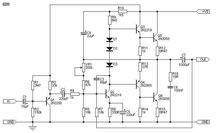
A Really Simple Power Amplifier
The amp was called "El Cheapo 2-30", and was rated at a maximum of 30W per channel into 16 Ohms. It used a single regulated power supply and capacitor coupled speaker. Having a scan of the original, the exact circuit...
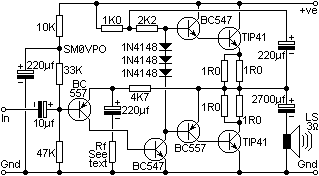
4 Watt audio Amplifier
The circuit is very simple and incorporates darlington output transistors that will provide more than enough output current than is needed to drive a 3-ohm speaker. The gain may be pre-set for a variety of input levels, making it suitable...