


400MHz differential amplifier OPA660 BUF601 schematic
#OPA660
#BUF601
#differential amplifier
#broadband
#400MHz
#RF
#high frequency
#operational amplifier
#signal processing
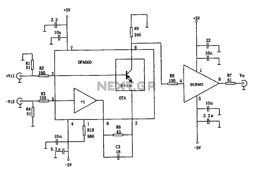
Description: The circuit presented is a 400MHz broadband differential amplifier. It comprises two main components: the incoming broadband differential amplifier integrated circuit OPA660 and the buffer amplifier BUF601. The voltage gain of the circuit is given by the formula Av = R9 / (R8 + 1/gm), where gm represents the transconductance of the OPA660 operational transconductance amplifier. Given that the resistance R10 is 560 ohms, the quiescent current for the OPA660 is approximately 10mA, resulting in a transconductance gm of 82mA/V.
The 400MHz broadband differential amplifier circuit is designed to amplify differential signals while rejecting common-mode noise, making it suitable for high-frequency applications. The OPA660 integrated circuit serves as the core amplification component, providing high-speed performance and low noise characteristics. It operates effectively in a differential configuration, which enhances its ability to process signals with minimal distortion.
The buffer amplifier BUF601 is used to isolate the output of the OPA660 from subsequent stages, ensuring that the load does not affect the amplifier's performance. The voltage gain of the circuit is calculated using the resistors R8 and R9, along with the transconductance value of the OPA660. The gain formula indicates that the gain can be adjusted by varying the values of R8 and R9, allowing for flexibility in the circuit's performance based on the specific application requirements.
The quiescent current of approximately 10mA is crucial for maintaining the linear operation of the OPA660, ensuring that it operates within its optimal range. The transconductance value of 82mA/V indicates the amplifier's ability to convert input voltage changes into proportional output current changes, which is essential for achieving the desired amplification characteristics.
Overall, this circuit configuration is ideal for applications requiring high-speed signal processing, such as in communication systems or high-frequency data acquisition systems, where fidelity and speed are paramount. As shown for the 400MHz broadband differential amplifier circuit. The circuit consists of two parts: the incoming broadband differential amplifier integrated chip OPA660 compos ition and the composition of the cache by the amplifying circuit BUF601. The voltage of the circuit magnification: Av R9/(R8 + 1/gm), where gm is the transconductance amplifier OTA OPA660 transconductance. Because the figure of the resistance R10 560, so the OPA660 quiescent current is about 10mA, this time the transconductance gm 82mA/V.
The 400MHz broadband differential amplifier circuit is designed to amplify differential signals while rejecting common-mode noise, making it suitable for high-frequency applications. The OPA660 integrated circuit serves as the core amplification component, providing high-speed performance and low noise characteristics. It operates effectively in a differential configuration, which enhances its ability to process signals with minimal distortion.
The buffer amplifier BUF601 is used to isolate the output of the OPA660 from subsequent stages, ensuring that the load does not affect the amplifier's performance. The voltage gain of the circuit is calculated using the resistors R8 and R9, along with the transconductance value of the OPA660. The gain formula indicates that the gain can be adjusted by varying the values of R8 and R9, allowing for flexibility in the circuit's performance based on the specific application requirements.
The quiescent current of approximately 10mA is crucial for maintaining the linear operation of the OPA660, ensuring that it operates within its optimal range. The transconductance value of 82mA/V indicates the amplifier's ability to convert input voltage changes into proportional output current changes, which is essential for achieving the desired amplification characteristics.
Overall, this circuit configuration is ideal for applications requiring high-speed signal processing, such as in communication systems or high-frequency data acquisition systems, where fidelity and speed are paramount. As shown for the 400MHz broadband differential amplifier circuit. The circuit consists of two parts: the incoming broadband differential amplifier integrated chip OPA660 compos ition and the composition of the cache by the amplifying circuit BUF601. The voltage of the circuit magnification: Av R9/(R8 + 1/gm), where gm is the transconductance amplifier OTA OPA660 transconductance. Because the figure of the resistance R10 560, so the OPA660 quiescent current is about 10mA, this time the transconductance gm 82mA/V.
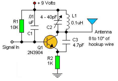
RF oscillator circuit (2N3904)
This basic RF oscillator circuit is easy to build and the components are not critical. Most of them can be found in your junk parts box. The L1 antenna coil can be made by close winding 8 to 10 turns...
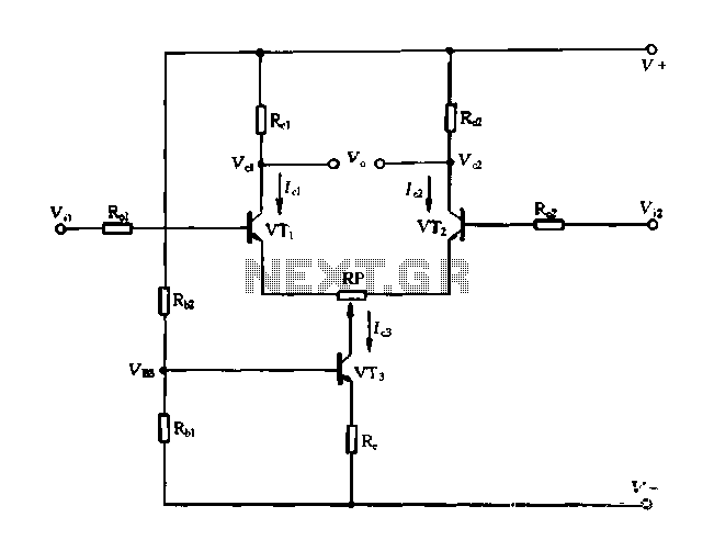
Differential circuit with constant current
A differential amplifier with a constant current source is illustrated in Figure 1-27. As long as capacitor C3 is maintained at a constant value, capacitors C1 and C2 cannot be simultaneously increased or decreased, preventing voltage drift. The differential circuit...
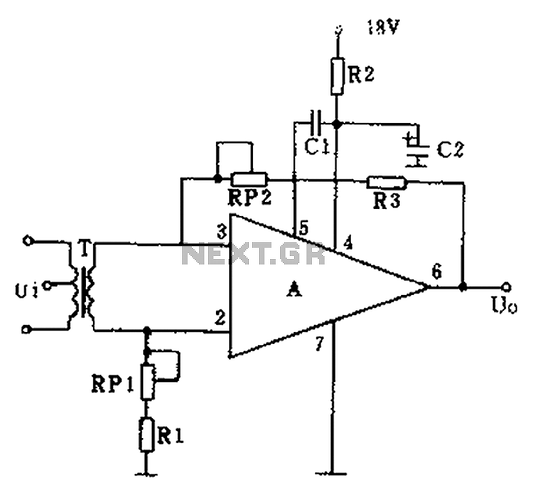
GF2A op amp audio amplifier circuit diagram
The operational amplifier A is utilized in an audio preamplifier circuit. Its advantages include compact size, low noise, low power consumption, and excellent consistency. The operational amplifier can achieve significant negative feedback while increasing output without distortion. The signal distortion...

High frequency switch
The 2N4391 features a low ON resistance of 30 ohms and a high OFF impedance of less than 0 pF when in the off state. With appropriate layout and an optimal switch configuration, the stated performance can be easily attained.
The...
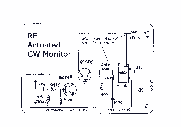
RF Actuated Keying Monitor
Sending Morse on a rig without a sidetone is not impossible, but is not particularly pleasant either. This battery-powered monitor has been designed to provide an audible indication of keying for those whose rigs lack a CW sidetone. Its sensor...
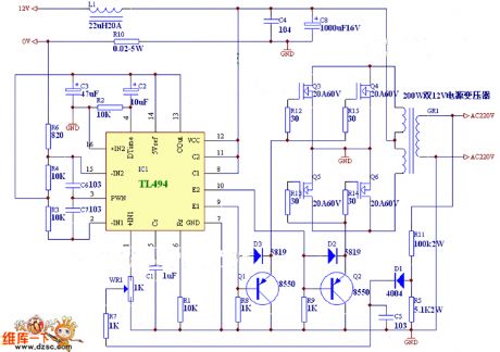
Precision current sink sourcel
An operational amplifier circuit can provide a constant voltage source with a high amplification factor and substantial load current. Even with significant variations in circuit parameters, the output voltage maintains high precision. The output current limit is managed by transistors...
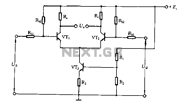
Differential amplifier circuit has a constant current source
The differential amplifier circuit features a constant current source.
The differential amplifier is a fundamental building block in analog electronics, utilized for amplifying the difference between two input voltages while rejecting any signals that are common to both inputs. Central to...
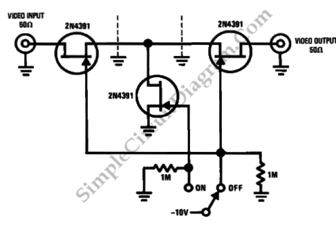
High Frequency Switch
This is a high-frequency switch circuit. This circuit utilizes the 2N4391 transistor. When in the off state, it provides a high off-impedance of less than 0.2 pF and exhibits a low on-resistance.
The high-frequency switch circuit designed with the 2N4391 transistor...
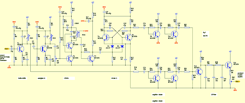
Amatorki projekt
The circuit is designed to add two identical branches to the existing despreading spectrum. The only difference between the branches is the phase of the PN sequences fed into each branch, specifically at the input of a double-balanced mixer. The...