


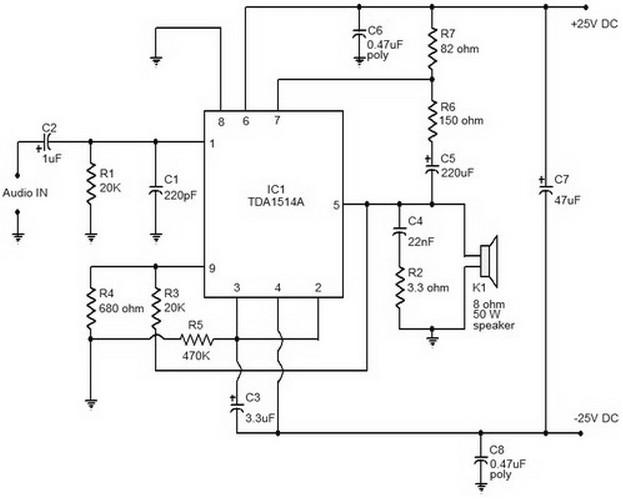
40W audio amplifier based on TDA1514 circuit diagram
Description: This document provides a circuit diagram of a car stereo. It includes a circuit diagram of a Class B 15 Watts audio amplifier designed using a dual op-amp and a transistor. The 15 W Class B audio amplifier circuit is based on the LM833 operational amplifier.
The car stereo circuit integrates various components to achieve high-quality audio output. The Class B audio amplifier is particularly noteworthy for its efficiency and ability to deliver a significant amount of power with minimal distortion. This amplifier uses two transistors, each responsible for amplifying one half of the audio signal, which is characteristic of Class B operation.
In the circuit, the LM833 dual op-amp serves as the input stage, providing necessary signal conditioning and gain before the signal is passed to the output stage. The op-amp configuration ensures that the audio signal is amplified with high fidelity. The output stage consists of complementary transistors that work in tandem to amplify the signal. This arrangement allows for a more efficient operation, reducing the heat generated compared to Class A amplifiers.
The circuit diagram typically includes power supply connections, input and output terminals, and biasing resistors that set the operating point of the transistors. Proper biasing is crucial for the linear operation of the transistors, ensuring that they do not enter cutoff or saturation during operation.
Additionally, capacitors may be included in the circuit to filter out noise and provide stability, while feedback resistors are used to control gain and improve linearity. The overall design ensures that the amplifier can drive speakers effectively, delivering a clean and powerful audio output suitable for automotive applications.Here is a circuit diagram of car stereo. Below is a circuit diagram of class B 15 Watts audio amplifier is designed using a dual op-amp and transistor. The 15 W class B audio amplifier circuit shown here is a simple class B audio amplifier based onLM833 op.
The car stereo circuit integrates various components to achieve high-quality audio output. The Class B audio amplifier is particularly noteworthy for its efficiency and ability to deliver a significant amount of power with minimal distortion. This amplifier uses two transistors, each responsible for amplifying one half of the audio signal, which is characteristic of Class B operation.
In the circuit, the LM833 dual op-amp serves as the input stage, providing necessary signal conditioning and gain before the signal is passed to the output stage. The op-amp configuration ensures that the audio signal is amplified with high fidelity. The output stage consists of complementary transistors that work in tandem to amplify the signal. This arrangement allows for a more efficient operation, reducing the heat generated compared to Class A amplifiers.
The circuit diagram typically includes power supply connections, input and output terminals, and biasing resistors that set the operating point of the transistors. Proper biasing is crucial for the linear operation of the transistors, ensuring that they do not enter cutoff or saturation during operation.
Additionally, capacitors may be included in the circuit to filter out noise and provide stability, while feedback resistors are used to control gain and improve linearity. The overall design ensures that the amplifier can drive speakers effectively, delivering a clean and powerful audio output suitable for automotive applications.Here is a circuit diagram of car stereo. Below is a circuit diagram of class B 15 Watts audio amplifier is designed using a dual op-amp and transistor. The 15 W class B audio amplifier circuit shown here is a simple class B audio amplifier based onLM833 op.

Fast Composite Amplifier Circuit
An ultra-low-noise, low-distortion operational amplifier, the AD797, is combined with the ADS 11 operational amplifier, which provides high bandwidth and a 100-mA output drive capability. This composite amplifier circuit is effective for driving high-resolution ADCs and ATE systems. The fast...
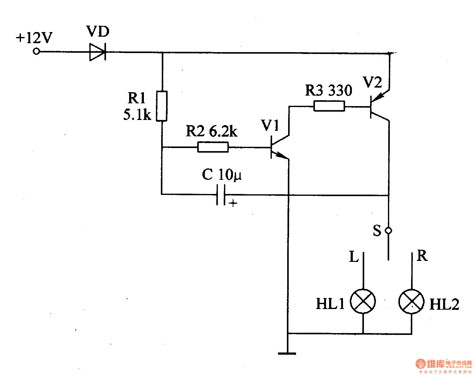
Motor vehicle steering flasher 12
The motor vehicle steering flasher described in the example utilizes high-power transistors as electronic switches, and the circuit is simple and easy to construct. The motor vehicle steering flasher consists of the flash circuit with resistors R1-R3, a capacitor C,...
11W Stereo/22W Mono Power Amp Using TDA1519C
Integrated AF power amplifiers have experienced significant advancements in recent years, offering enhanced power and ease of use. The TDA1519C from Philips features two power amplifiers that provide 11 W per channel in stereo mode or 22 W in mono...
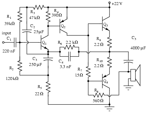
Amplifier circuits
Note that Q3 and Q4 in the figure below are complementary, with Q3 being an NPN transistor and Q4 being a PNP transistor. This circuit is suitable for moderate power audio amplifiers. For a detailed explanation of this circuit, refer...
Reverse Bias Oscillators
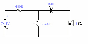
Several NPN transistors can oscillate within the audio frequency range when reverse biased. The minimum supply voltage required is 7V for low-power transistors like the BC109, BC238, and 2N2222A; it increases to 12V for medium-power transistors such as the BD139,...
TBA810 - 7 Watt Audio Amplifier Circuit
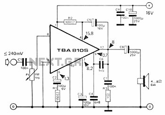
This circuit is a 7 Watt audio amplifier that is simple and easy to construct. It utilizes the TBA810 as the primary component, supported by a few passive components. The amplifier operates effectively, and the necessary kits and components are...

Single-op-amp-clock
Capacitor C1 is charged through timing resistor R1 when the clock output is high. When C1 reaches the upper threshold voltage, the output signal decreases, and then C1 discharges through R1 until its voltage reaches the lower threshold point. When...
2 Transistor LED Flasher
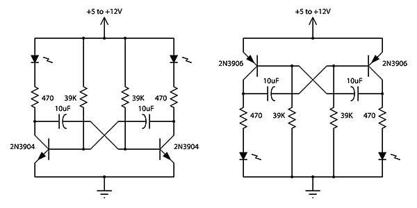
This is a classic 2-transistor astable multivibrator. Many other NPN small signal or switching transistors can be used, including 2N4401, PN2222, or 2N2222 using the circuit on the left. The circuit can also be inverted using PNP transistors such as...

Multi-Zone Transistor-Based Intruder Alarm
This is a simple transistor-based burglar alarm circuit. Its features include automatic exit and entry delays, along with a timed bell cut-off and reset. It is designed to be used with standard types of normally-closed input devices such as magnetic...