


45 Watt Class-B Audio Power Amplifier
#audio
#Class-B
#power amplifier
#op-amp
#BJT
#common-emitter
#discrete-components
#complementary output stage
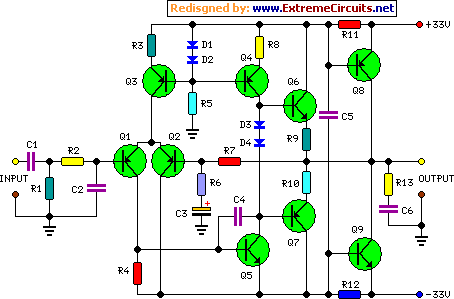
Description: The goals were achieved by utilizing a discrete-component operational amplifier (op-amp) driving a bipolar junction transistor (BJT) complementary common-emitter output stage configured for Class B operation. In this configuration, the output transistors remain off for small output currents, allowing the op-amp to supply the entire output current. As output currents increase, the power transistors become active, limiting the op-amp's contribution to approximately 0.7/R11. The quiescent current of the op-amp biases the external transistors, significantly reducing crossover distortion. This concept originated from a letter published in Wireless World, December 1982, by N. M. Allinson from the University of Keele, Staffordshire. The letter discussed the use of op-amp integrated circuits as drivers, but due to the requirement for supply voltages of up to ±35V for a 50W amplifier, a discrete-component op-amp was considered, which proved to be a beneficial choice. The discrete-component op-amp is based on a design by Douglas Self, although his original circuit featured a Class A output stage. For optimal performance of this amplifier, a Class B output stage op-amp was necessary, leading to modifications of the original circuit. By employing a mains transformer with a secondary winding rated at the standard value of 25 + 25V (or 24 + 24V) and a power rating of 100/120VA, two amplifiers can be driven to output powers of 45W and 69W into 8 and 4 Ohms, respectively, while maintaining very low distortion levels (less than 0.01% at 1kHz and 20W into 8 Ohms). This straightforward yet robust circuit, designed for high-quality audio applications and to complement a series of articles on the Modular Preamplifier Control Center, is also well-suited for creating an excellent guitar or bass amplifier.
The described circuit utilizes a discrete operational amplifier designed to drive a complementary BJT output stage configured for Class B operation. The use of discrete components allows for higher voltage ratings and customization of the amplifier's characteristics, which is particularly advantageous for high-power audio applications.
In the circuit, the op-amp operates in conjunction with the output transistors to manage the current flow effectively. For low output currents, the op-amp is responsible for supplying the output current entirely, thus avoiding the inefficiencies associated with the output transistors. As the output current requirement increases, the output transistors begin to conduct, taking over the output current supply while the op-amp contributes minimally, as defined by the formula 0.7/R11. This design choice minimizes crossover distortion, a common issue in amplifiers, by ensuring that the quiescent current from the op-amp keeps the external transistors biased adequately.
The transformer specifications of 25 + 25V or 24 + 24V with a power rating of 100/120VA are critical for providing the necessary power to achieve the desired output levels of 45W into 8 Ohms and 69W into 4 Ohms. The design emphasizes low distortion, ensuring that audio signals remain clear and accurate, even at higher power levels.
This amplifier circuit is versatile and can be applied in various audio applications, including as a high-fidelity audio amplifier or as a dedicated guitar or bass amplifier. Its rugged construction and straightforward design make it suitable for both professional and amateur audio environments, enhancing the overall audio experience.These goals were achieved by using a discrete-components op-amp driving a BJT complementary common-emitter output stage into Class B operation. In this way, for small output currents, the output transistors are turned off, and the op-amp provides all of the output current.
At higher output currents, the power transistors conduct, and the contribution of the op-amp is limited to approximately 0. 7/R11. The quiescent current of the op-amp biases the external transistors, and hence greatly reduces the range of crossover. The idea sprang up from a letter published on Wireless World, December 1982, page 65 written by N. M. Allinson, then at the University of Keele, Staffordshire. In this letter, op-amp ICs were intended as drivers but, as supply voltages up to +/- 35V are required for an amplifier of about 50W, the use of an op-amp made of discrete-components was then considered and the choice proved rewarding.
The discrete-components op-amp is based on a Douglas Self design. Nevertheless, his circuit featured quite obviously a Class A output stage. As for proper operation of this amplifier a Class B output stage op-amp is required, the original circuit was modified accordingly. Using a mains transformer with a secondary winding rated at the common value of 25 + 25V (or 24 + 24V) and 100/120VA power, two amplifiers can be driven at 45W and 69W output power into 8 and 4 Ohms respectively, with very low distortion (less than 0.
01% @ 1kHz and 20W into 8 Ohms). This simple, straightforward but rugged circuit, though intended for any high quality audio application and, above all, to complete the recently started series of articles forming the Modular Preamplifier Control Center, is also well suited to make a very good Guitar or Bass amplifier. Enjoy!
The described circuit utilizes a discrete operational amplifier designed to drive a complementary BJT output stage configured for Class B operation. The use of discrete components allows for higher voltage ratings and customization of the amplifier's characteristics, which is particularly advantageous for high-power audio applications.
In the circuit, the op-amp operates in conjunction with the output transistors to manage the current flow effectively. For low output currents, the op-amp is responsible for supplying the output current entirely, thus avoiding the inefficiencies associated with the output transistors. As the output current requirement increases, the output transistors begin to conduct, taking over the output current supply while the op-amp contributes minimally, as defined by the formula 0.7/R11. This design choice minimizes crossover distortion, a common issue in amplifiers, by ensuring that the quiescent current from the op-amp keeps the external transistors biased adequately.
The transformer specifications of 25 + 25V or 24 + 24V with a power rating of 100/120VA are critical for providing the necessary power to achieve the desired output levels of 45W into 8 Ohms and 69W into 4 Ohms. The design emphasizes low distortion, ensuring that audio signals remain clear and accurate, even at higher power levels.
This amplifier circuit is versatile and can be applied in various audio applications, including as a high-fidelity audio amplifier or as a dedicated guitar or bass amplifier. Its rugged construction and straightforward design make it suitable for both professional and amateur audio environments, enhancing the overall audio experience.These goals were achieved by using a discrete-components op-amp driving a BJT complementary common-emitter output stage into Class B operation. In this way, for small output currents, the output transistors are turned off, and the op-amp provides all of the output current.
At higher output currents, the power transistors conduct, and the contribution of the op-amp is limited to approximately 0. 7/R11. The quiescent current of the op-amp biases the external transistors, and hence greatly reduces the range of crossover. The idea sprang up from a letter published on Wireless World, December 1982, page 65 written by N. M. Allinson, then at the University of Keele, Staffordshire. In this letter, op-amp ICs were intended as drivers but, as supply voltages up to +/- 35V are required for an amplifier of about 50W, the use of an op-amp made of discrete-components was then considered and the choice proved rewarding.
The discrete-components op-amp is based on a Douglas Self design. Nevertheless, his circuit featured quite obviously a Class A output stage. As for proper operation of this amplifier a Class B output stage op-amp is required, the original circuit was modified accordingly. Using a mains transformer with a secondary winding rated at the common value of 25 + 25V (or 24 + 24V) and 100/120VA power, two amplifiers can be driven at 45W and 69W output power into 8 and 4 Ohms respectively, with very low distortion (less than 0.
01% @ 1kHz and 20W into 8 Ohms). This simple, straightforward but rugged circuit, though intended for any high quality audio application and, above all, to complete the recently started series of articles forming the Modular Preamplifier Control Center, is also well suited to make a very good Guitar or Bass amplifier. Enjoy!
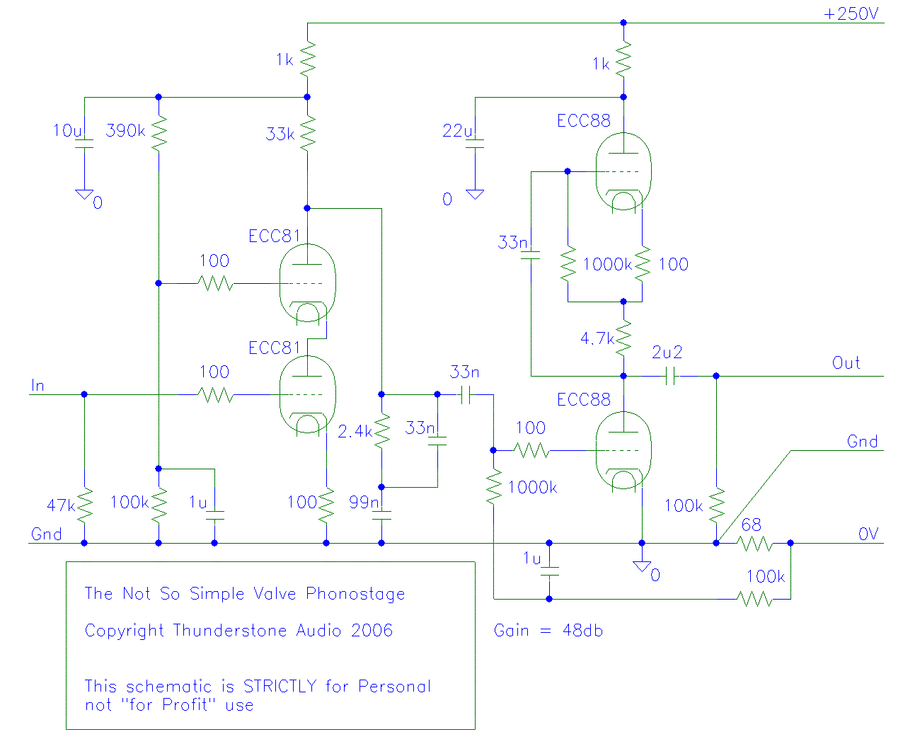
New Phono amp
Very interesting points Chris and Thorsten, but I would like to take a moment to revisit my latest design, which is represented in the attached schematic.
The attached schematic represents a recent design that integrates various electronic components to achieve a...
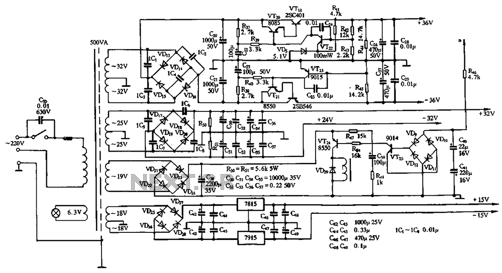
Power amplifier circuit diamond differential input
The power supply circuits for servo systems are critical during both the adoption and operational stages.
The power supply circuit for servo systems is designed to provide stable and adequate voltage and current levels necessary for the servo motors to function...
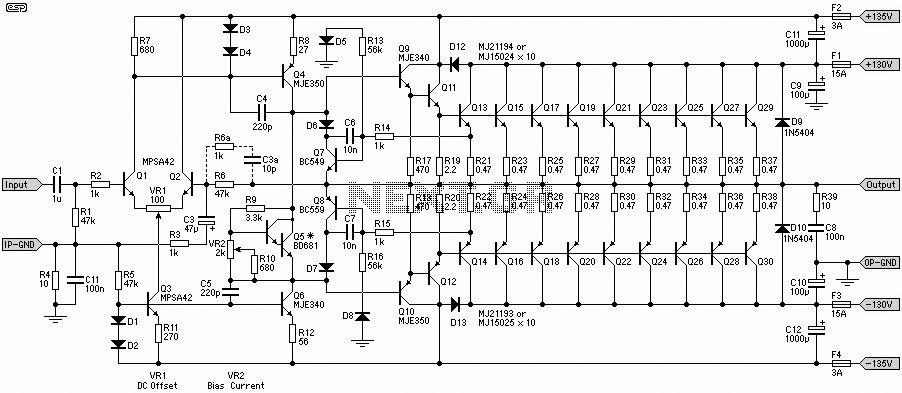
1500W Power Amplifier
A 1500W power amplifier circuit design diagram created by Rod Elliott. The circuit utilizes 10 pairs of power transistors, specifically MJ15024 and MJ15025, or alternatively MJ21193 and MJ21194.
The 1500W power amplifier circuit is designed for high-performance audio applications, providing significant...
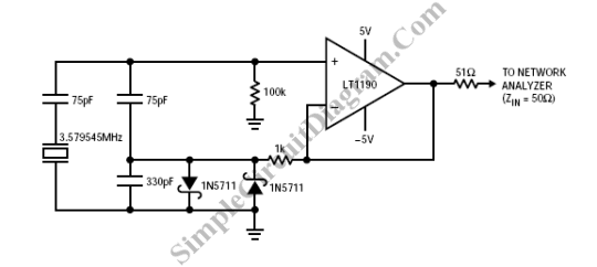
Op-Amp Colpitts Oscillator
A Colpitts oscillator can be implemented using an operational amplifier, provided that the op-amp has an appropriate bandwidth. An example of such a circuit can utilize the LT1190 or LT1191.
The Colpitts oscillator is a type of electronic oscillator that generates...
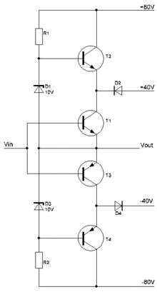
amplifier 1
A power amplifier is an amplifier designed to deliver maximum power output to a load. For example, in an audio system, it is the component responsible for driving speakers.
A power amplifier is a critical component in various electronic systems, particularly...
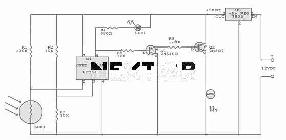
Mooring Light Controller
Integrated-circuit U1-an LF351 or 741 op amp-is used as a comparator to control the light. Resistors R2 and R3 provide a reference voltage of about 2.5 volts at pin 3 of U1. When daylight falls on light-dependent resistor LDR1, its...

High output 600 Ohm line driver
The circuit features a "floating" output, functioning similarly to an isolated transformer winding. The output amplitude remains constant regardless of whether the center or either end of the load is grounded. This is accomplished by ensuring that the output impedance...
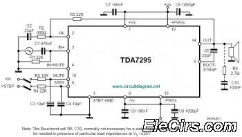
TDA7295 80W Audio Amplifier
The IC TDA7295 is a monolithic integrated circuit designed for use as an audio class AB amplifier in high-fidelity applications, including home theaters and high-end televisions.
The TDA7295 is a versatile audio amplifier that delivers high-quality sound reproduction, making it suitable...
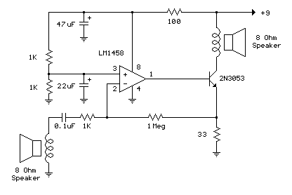
Low Power Op-Amp - Audio Amp (50 milliwatt) circuit
The example below illustrates the use of an operational amplifier (op-amp) as an audio amplifier in a basic intercom system. A small 8-ohm speaker is utilized as a microphone, which is connected to the op-amp input through a 0.1 µF...