


60W Linear amplifiers
#linear amplifier
#IRF840
#power MOSFET
#60W
#solid state
#audio amplifier
#power transistor
#inverter
#SMPS
#electronics
Description: The 60 Watt linear amplifier is a straightforward all-solid-state circuit utilizing the power MOSFET IRF840. The IRF series of power transistors are available in various voltage and power ratings. A single IRF840 can handle a maximum power output of 125 watts. Since these transistors are commonly used in inverters and switch-mode power supplies (SMPS), they are easily obtainable for around Rs: 20. The linear amplifier can be connected to the output of the popular VWN-QRP to achieve an output of 60 Watts. The circuit draws 700 mA at a supply voltage of 60 Volts (Vcc). A good heat sink is essential for the power transistor. Circuit alignment is straightforward; connect a dummy load to the output of the circuit. A small bulb, such as a 24V 6W bulb, can serve as the dummy load. A 230V 60W bulb has also been used successfully as a dummy load with the IRF840 power amplifier operating at 120 Volts. The 10K preset should be adjusted to achieve approximately 100 mA of drain current. A gate voltage of 0.8V was used with the linear amplifier. A high gate voltage can cause the power transistor to be destroyed by self-oscillation, so the gate voltage must remain below 2V, with a fixed value of 1V being safe. The coil on the drain of the IRF consists of 3 turns of 20 SWG wire wound on four T13.9 toroids (two toroids are stacked to form a balun core). The RFC on the Vcc line is composed of 20 turns of 20 SWG wire wound on a T20 toroid.
The 60 Watt linear amplifier circuit is designed for efficient amplification of RF signals, leveraging the capabilities of the IRF840 MOSFET. This device is characterized by its high power output and robust thermal performance, making it suitable for various applications in amateur radio and RF transmission.
The amplifier's configuration allows for a maximum output power of 60 Watts while drawing a current of 700 mA at 60 Volts. The choice of the IRF840 is strategic, as its maximum power handling capability of 125 Watts ensures reliable performance under typical operating conditions. The circuit's simplicity is enhanced by the use of a single MOSFET, which simplifies alignment and troubleshooting.
To prevent thermal overload, it is imperative to use an adequate heat sink to dissipate heat generated during operation. The alignment procedure involves connecting a dummy load, such as a small bulb, which serves as a safe testing method to monitor the output without risking damage to the amplifier. The use of a 10K preset resistor allows for fine-tuning of the drain current, targeting approximately 100 mA for optimal performance.
The gate voltage is a critical parameter that must be managed carefully. Operating the gate voltage at 0.8V minimizes the risk of self-oscillation, a phenomenon that can lead to catastrophic failure of the MOSFET. The design specifies a maximum gate voltage of 2V, with 1V being the recommended operating point to ensure reliability.
The output stage includes a coil wound on the drain of the IRF840, consisting of 3 turns of 20 SWG wire on a balun core formed by stacking two T13.9 toroids. This configuration aids in impedance matching and enhances the amplifier's performance. Additionally, the RFC (Radio Frequency Choke) on the Vcc line is constructed from 20 turns of 20 SWG wire on a T20 toroid, which helps in filtering out unwanted RF signals and stabilizing the power supply.
Overall, this linear amplifier circuit exemplifies a well-thought-out design that balances performance, simplicity, and reliability, making it an excellent choice for amateur radio enthusiasts and RF applications.The 60 Watt linear amplifier is simple all solid state circuit using power mosfet IRF840. The IRF series of power transistors are available in various voltage and power ratings. A single IRF840 can handle maximum power output of 125 watts. Since these transistors are used in inverters and smps they are easily available for around Rs: 20/-. The IRF linear amplifier can be connected to the out put of popular VWN-QRP to get an output of 60 Watts. The circuit draws 700 ma at 60 Volt Vcc. Good heat sink is a must for the power transistor. Alignment of the circuit is very easy. Connect a dummy load to the out put of the circuit. You can use some small bulb like 24V 6Watts as the dummy load. I have even used 230V 60Watts bulb as dummy load with my IRF840 power amplifier working at 120Volts. Adjust the 10K preset to get around 100 ma Drain current. I used gate voltage of 0. 8V with my linear amplifier. A heigh gate voltage can make the power transistor get distroyed by self oscillation. So gate voltage must be below 2V and fixing at 1V will be safe. The coil on the drain of IRF is 3 turns 20 SWG wound on 4 number of T13. 9 torroids (two torroids are stacked to form a balun core). The RFC at the Vcc line is 20 Turns 20 SWG wound on T20 torroid.
The 60 Watt linear amplifier circuit is designed for efficient amplification of RF signals, leveraging the capabilities of the IRF840 MOSFET. This device is characterized by its high power output and robust thermal performance, making it suitable for various applications in amateur radio and RF transmission.
The amplifier's configuration allows for a maximum output power of 60 Watts while drawing a current of 700 mA at 60 Volts. The choice of the IRF840 is strategic, as its maximum power handling capability of 125 Watts ensures reliable performance under typical operating conditions. The circuit's simplicity is enhanced by the use of a single MOSFET, which simplifies alignment and troubleshooting.
To prevent thermal overload, it is imperative to use an adequate heat sink to dissipate heat generated during operation. The alignment procedure involves connecting a dummy load, such as a small bulb, which serves as a safe testing method to monitor the output without risking damage to the amplifier. The use of a 10K preset resistor allows for fine-tuning of the drain current, targeting approximately 100 mA for optimal performance.
The gate voltage is a critical parameter that must be managed carefully. Operating the gate voltage at 0.8V minimizes the risk of self-oscillation, a phenomenon that can lead to catastrophic failure of the MOSFET. The design specifies a maximum gate voltage of 2V, with 1V being the recommended operating point to ensure reliability.
The output stage includes a coil wound on the drain of the IRF840, consisting of 3 turns of 20 SWG wire on a balun core formed by stacking two T13.9 toroids. This configuration aids in impedance matching and enhances the amplifier's performance. Additionally, the RFC (Radio Frequency Choke) on the Vcc line is constructed from 20 turns of 20 SWG wire on a T20 toroid, which helps in filtering out unwanted RF signals and stabilizing the power supply.
Overall, this linear amplifier circuit exemplifies a well-thought-out design that balances performance, simplicity, and reliability, making it an excellent choice for amateur radio enthusiasts and RF applications.The 60 Watt linear amplifier is simple all solid state circuit using power mosfet IRF840. The IRF series of power transistors are available in various voltage and power ratings. A single IRF840 can handle maximum power output of 125 watts. Since these transistors are used in inverters and smps they are easily available for around Rs: 20/-. The IRF linear amplifier can be connected to the out put of popular VWN-QRP to get an output of 60 Watts. The circuit draws 700 ma at 60 Volt Vcc. Good heat sink is a must for the power transistor. Alignment of the circuit is very easy. Connect a dummy load to the out put of the circuit. You can use some small bulb like 24V 6Watts as the dummy load. I have even used 230V 60Watts bulb as dummy load with my IRF840 power amplifier working at 120Volts. Adjust the 10K preset to get around 100 ma Drain current. I used gate voltage of 0. 8V with my linear amplifier. A heigh gate voltage can make the power transistor get distroyed by self oscillation. So gate voltage must be below 2V and fixing at 1V will be safe. The coil on the drain of IRF is 3 turns 20 SWG wound on 4 number of T13. 9 torroids (two torroids are stacked to form a balun core). The RFC at the Vcc line is 20 Turns 20 SWG wound on T20 torroid.
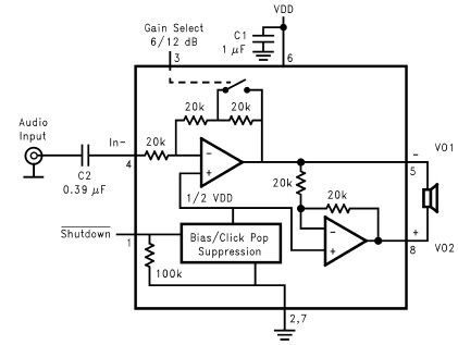
LM4096 audio amplifier circuit design
The LM4096 audio amplifier circuit diagram represents a straightforward audio amplifier capable of delivering a maximum output power of 1 watt, utilizing a minimal number of external electronic components. The LM4906, an audio power amplifier, is specifically engineered for demanding...
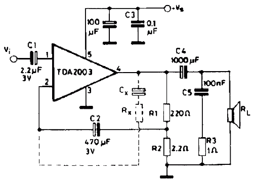
10W audio amplifier with TDA2003
The TDA2003 offers enhanced performance while retaining the same pin configuration as the TDA2002. It maintains the advantageous features of the TDA2002, including a minimal number of external components, ease of assembly, and savings in both space and cost. This...
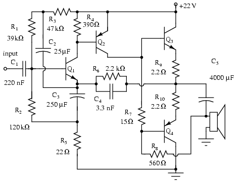
Amplifier circuits
Note that Q3 and Q4 in the figure below are complementary, with Q3 being an NPN transistor and Q4 being a PNP transistor. This circuit is suitable for moderate power audio amplifiers. For a detailed explanation of this circuit, refer...
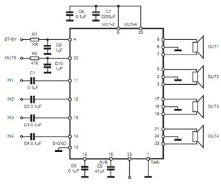
electronic circuit amplifier
The TDA7383 features a fully complementary PNP/NPN output configuration, enabling a rail-to-rail output voltage swing without the need for bootstrap capacitors. This design significantly reduces the component count, allowing for compact assemblies. An integrated clipping detector facilitates gain compression operations,...
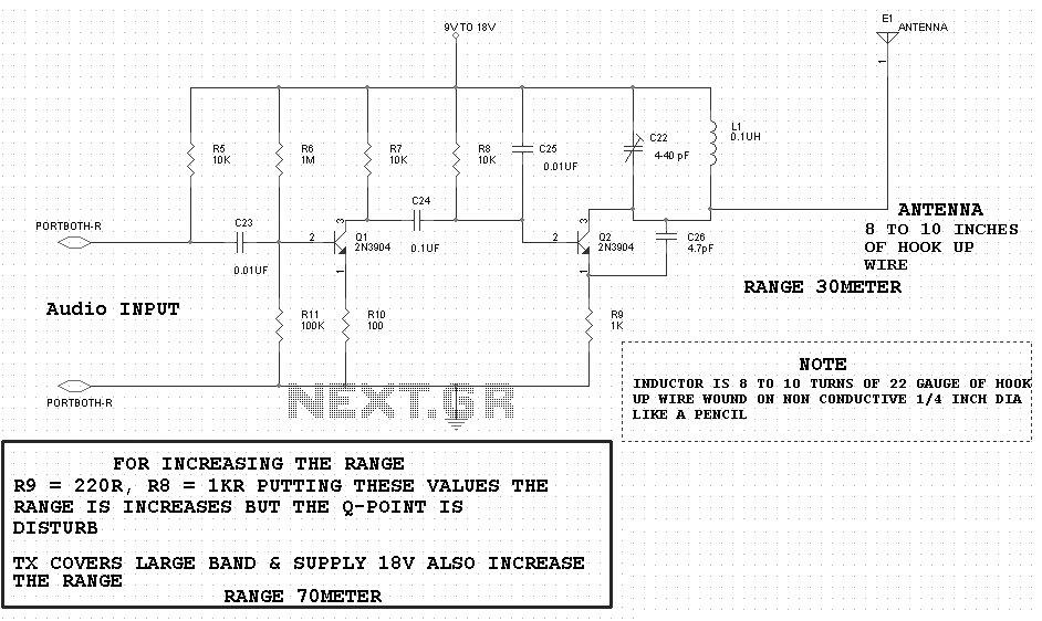
60W Linear Amplifier
This circuit utilizes the power MOSFET IRF840 for a 60-watt linear amplifier. The IRF series of power transistors are available in various voltage and current ratings.
The described circuit employs the IRF840, which is a high-voltage N-channel MOSFET, suitable for applications...
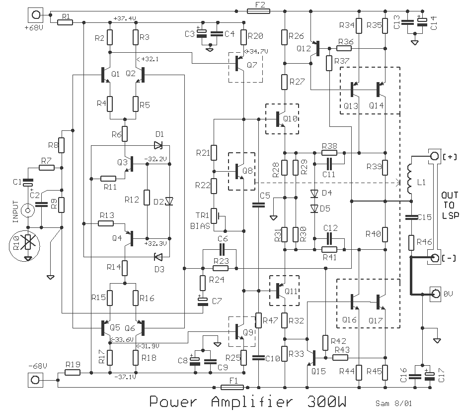
300 Watt audio Amplifier
For many applications, there's no substitute for sheer power - low efficiency speakers, outdoor sound systems, or maybe you like the full flavor of the dynamic range of a high power amp. Whatever your requirement, this super power module should...
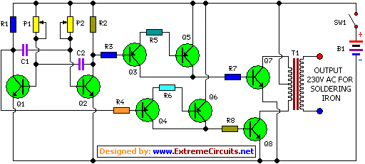
Inverter Circuit For Soldering Iron
This is a simple and cost-effective inverter designed to power a small soldering iron (25W, 35W, etc.) in situations where a mains supply is unavailable. The circuit utilizes eight transistors.
The inverter circuit operates by converting DC voltage from a battery...
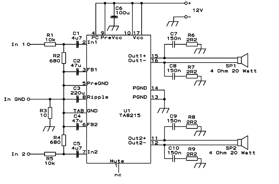
Audio IC TA8215 based on 15W Car Audio Amplifier
This circuit is designed as a stereo BTL (Bridge-Tied Load) 15W audio power amplifier using the TA8215 integrated circuit developed by Toshiba. Two TA8215 ICs are utilized in this configuration to achieve four output channels, with each IC providing two...
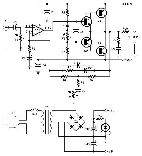
10W Audio Amplifier with Bass-boost
This design is based on an 18 Watt Audio Amplifier and was developed primarily to address the needs of users who have difficulty locating the TLE2141C chip. It utilizes the commonly available NE5532 Dual IC; however, its power output will...