


A 4 Watt Amplifier Portable RadioCircuit Design using TDA1011
#TDA1011
#portable radio
#4 watt
#Philips Semiconductor
#audio amplifier
#schematic
#circuit design
#low power
#radio application
#amplifier circuit
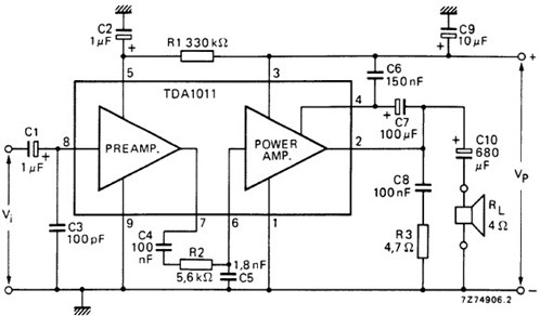
Description: The following schematic illustrates the design of a 4 Watt Amplifier Circuit Diagram intended for portable radio applications, utilizing the TDA1011 integrated circuit from Philips Semiconductor.
The 4 Watt Amplifier Circuit is designed to provide audio amplification in portable radio devices, ensuring sufficient power output for driving small speakers. The TDA1011 is a high-performance audio amplifier IC that offers low distortion and high efficiency, making it suitable for battery-operated applications.
The circuit typically includes the following components: the TDA1011 IC, resistors, capacitors, and a power supply. The input signal is fed into the amplifier through the input capacitor, which blocks any DC component while allowing the AC audio signal to pass. The gain of the amplifier can be set using external resistors connected to the feedback loop, allowing for customization based on the application requirements.
Power supply considerations are crucial; the TDA1011 operates efficiently within a specified voltage range, typically between 9V to 15V. Bypass capacitors are used near the power supply pins of the IC to filter out any noise and ensure stable operation.
The output stage of the amplifier is designed to drive a speaker directly, often with a series output capacitor to block DC voltage from reaching the speaker. This configuration helps to protect the speaker and improve sound quality.
Thermal management is also an essential aspect, as the amplifier can generate heat during operation. Adequate heat sinking or thermal pads may be necessary to dissipate heat and maintain optimal performance.
Overall, this amplifier circuit is ideal for portable radio applications, providing an effective solution for audio amplification while maintaining low power consumption and high sound quality.The following schematic depicts the design of a 4 Watt Amplifier Circuit Diagram for portable radio application using TDA1011 from Philips Semiconductor. The..
The 4 Watt Amplifier Circuit is designed to provide audio amplification in portable radio devices, ensuring sufficient power output for driving small speakers. The TDA1011 is a high-performance audio amplifier IC that offers low distortion and high efficiency, making it suitable for battery-operated applications.
The circuit typically includes the following components: the TDA1011 IC, resistors, capacitors, and a power supply. The input signal is fed into the amplifier through the input capacitor, which blocks any DC component while allowing the AC audio signal to pass. The gain of the amplifier can be set using external resistors connected to the feedback loop, allowing for customization based on the application requirements.
Power supply considerations are crucial; the TDA1011 operates efficiently within a specified voltage range, typically between 9V to 15V. Bypass capacitors are used near the power supply pins of the IC to filter out any noise and ensure stable operation.
The output stage of the amplifier is designed to drive a speaker directly, often with a series output capacitor to block DC voltage from reaching the speaker. This configuration helps to protect the speaker and improve sound quality.
Thermal management is also an essential aspect, as the amplifier can generate heat during operation. Adequate heat sinking or thermal pads may be necessary to dissipate heat and maintain optimal performance.
Overall, this amplifier circuit is ideal for portable radio applications, providing an effective solution for audio amplification while maintaining low power consumption and high sound quality.The following schematic depicts the design of a 4 Watt Amplifier Circuit Diagram for portable radio application using TDA1011 from Philips Semiconductor. The..
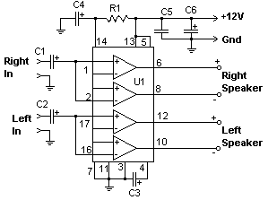
22 Watt Audio Amplifier
The 22 watt amp is easy to build, and very inexpensive. The circuit can be used as a booster in a car audio system, an amp for satellite speakers in a surround sound or home theater system, or as an...
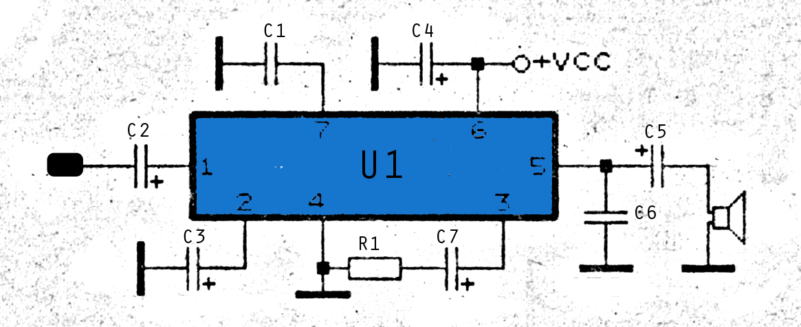
015Watt amplifier schematic
The amplifier circuit is highly suitable for use in FM radio receivers. It requires a supply voltage of 8 to 25 Volt DC and can deliver a maximum output power of 0.15W. Refer to the schematic below.
The described amplifier circuit...
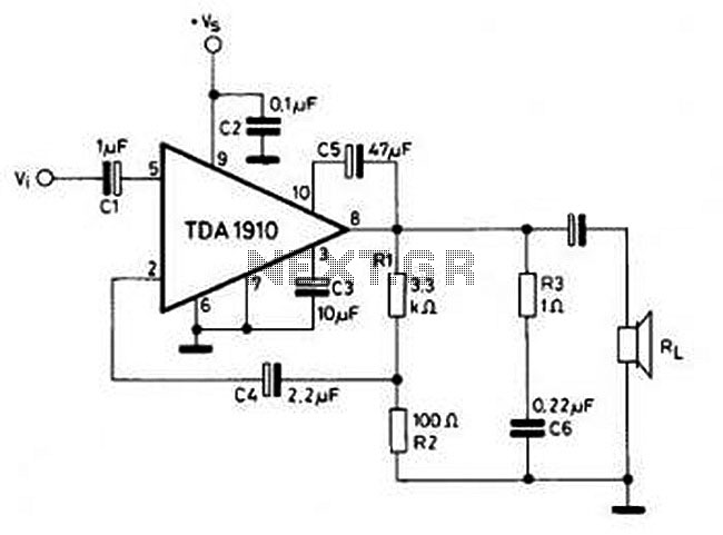
10w audio amplifier circuit
This circuit is simple and inexpensive, which is its primary advantage. Although the output power is not high, the audio quality is good due to the TDA1910's very low noise feature. This circuit is suitable for use as a student...
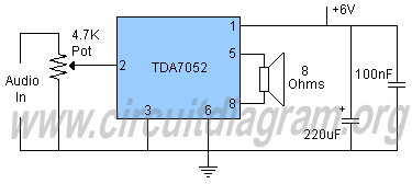
2 watt amplifier tda7052
Schematic diagram and description of a 2-watt audio amplifier circuit using the TDA7052 amplifier IC. This is a very simple audio amplifier circuit.
The 2-watt audio amplifier circuit utilizing the TDA7052 integrated circuit (IC) is designed for basic audio amplification applications....
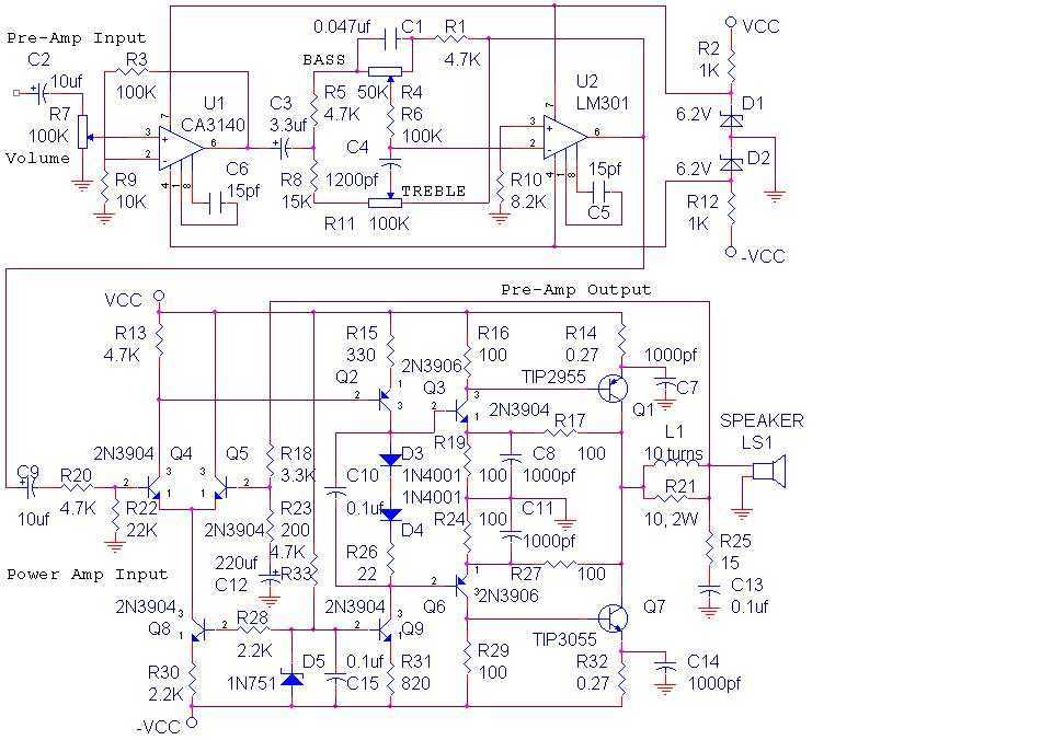
14 Watt Audio Amplifier
The audio amplifier shown below provides 14 watts of power, but can provide much more simply by increasing the power supply voltage. This amp was built in 1975 and has worked reliably ever since. The power amp portion was published...

Mini-box 2W Amplifier
This amplifier was designed to be self-contained in a small loudspeaker box. It can be fed by Walkman, Mini-Disc, iPod, CD players, computers, and similar devices fitted with line or headphone output. Of course, in most cases, you will have...
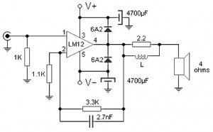
100 W audio amplifier based LM12CLK
The 100W audio power amplifier is powered by the integrated circuit LM12CLK, which is an operational power amplifier.
The 100W audio power amplifier utilizing the LM12CLK integrated circuit is designed to deliver high-quality audio output with significant power handling capabilities. The...
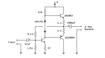
50mW amplifier schematic
Here is a little audio amplifier similar to what you might find in a small transistor radio. The input stage is biased so that the supply voltage is divided equally across the two complimentary output transistors which are slightly biased...
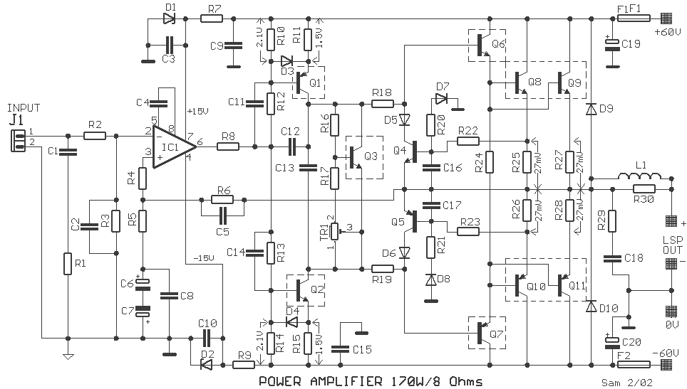
170 Watt audio amplifier
In the drawing, a simple but powerful power amplifier is presented. Its difference from classic designs, which use differential amplifiers in their input, is that this amplifier uses a complete NE5534 at its input. Thus, it is necessary to reduce...