


A combination of common-source grounded base amplifier formed by cascaded amplifier
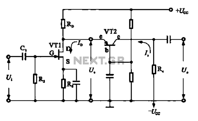
Description: A combination of a common-source grounded base amplifier formed by cascaded amplifiers. The source is grounded, and a common base amplifier is combined into a cascaded amplifier. The graph below shows the low noise characteristics of the FET common-base amplifier, which is used for amplifying high-frequency adaptive end units. This configuration is often employed as a wideband low noise preamplifier.
The described circuit configuration consists of a cascaded amplifier system that integrates a common-source amplifier with a common-base amplifier. The common-source amplifier provides high voltage gain and is characterized by its input impedance, which is typically high. This makes it suitable for interfacing with various signal sources. The grounded source configuration ensures stability and minimizes distortion, making it ideal for low-noise applications.
The common-base amplifier, on the other hand, is known for its low input impedance and high output impedance. This configuration is particularly effective for high-frequency applications, as it provides a wide bandwidth and is less susceptible to the Miller effect, which can limit bandwidth in other amplifier configurations. The cascading of these two amplifier types allows for the benefits of each to be utilized, creating a hybrid amplifier that is capable of amplifying weak signals while maintaining low noise levels.
In practical applications, such as adaptive end units, this cascaded amplifier configuration serves as a preamplifier. It is designed to enhance the signal level before further processing, ensuring that the subsequent stages of the system can operate effectively with a strong, low-noise signal. The low noise characteristics of the FET (Field Effect Transistor) used in the common-base stage are crucial for maintaining signal integrity, especially in high-frequency environments.
Overall, the combination of a grounded source common-source amplifier and a common-base amplifier in a cascaded configuration results in a versatile and efficient low-noise preamplifier suitable for a variety of applications, particularly in telecommunications and signal processing.A combination of common-source grounded base amplifier formed by cascaded amplifier The source is grounded and common base amplifier combined into a cascaded amplifier. The gra ph below shows the low noise of the FET, common- base amplifier for amplifying the high frequency adaptive end units produced cascaded amplifier, often as a wideband low noise preamplifier amplifier.
The described circuit configuration consists of a cascaded amplifier system that integrates a common-source amplifier with a common-base amplifier. The common-source amplifier provides high voltage gain and is characterized by its input impedance, which is typically high. This makes it suitable for interfacing with various signal sources. The grounded source configuration ensures stability and minimizes distortion, making it ideal for low-noise applications.
The common-base amplifier, on the other hand, is known for its low input impedance and high output impedance. This configuration is particularly effective for high-frequency applications, as it provides a wide bandwidth and is less susceptible to the Miller effect, which can limit bandwidth in other amplifier configurations. The cascading of these two amplifier types allows for the benefits of each to be utilized, creating a hybrid amplifier that is capable of amplifying weak signals while maintaining low noise levels.
In practical applications, such as adaptive end units, this cascaded amplifier configuration serves as a preamplifier. It is designed to enhance the signal level before further processing, ensuring that the subsequent stages of the system can operate effectively with a strong, low-noise signal. The low noise characteristics of the FET (Field Effect Transistor) used in the common-base stage are crucial for maintaining signal integrity, especially in high-frequency environments.
Overall, the combination of a grounded source common-source amplifier and a common-base amplifier in a cascaded configuration results in a versatile and efficient low-noise preamplifier suitable for a variety of applications, particularly in telecommunications and signal processing.A combination of common-source grounded base amplifier formed by cascaded amplifier The source is grounded and common base amplifier combined into a cascaded amplifier. The gra ph below shows the low noise of the FET, common- base amplifier for amplifying the high frequency adaptive end units produced cascaded amplifier, often as a wideband low noise preamplifier amplifier.
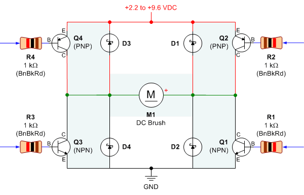
Bipolar Transistor HBridge Motor Driver
Schematic, breadboard photo, parts list, and results of several transistor variations on the classic bipolar H-bridge motor driver circuit.
The classic bipolar H-bridge motor driver circuit is a widely used configuration that allows for the control of DC motors in both...
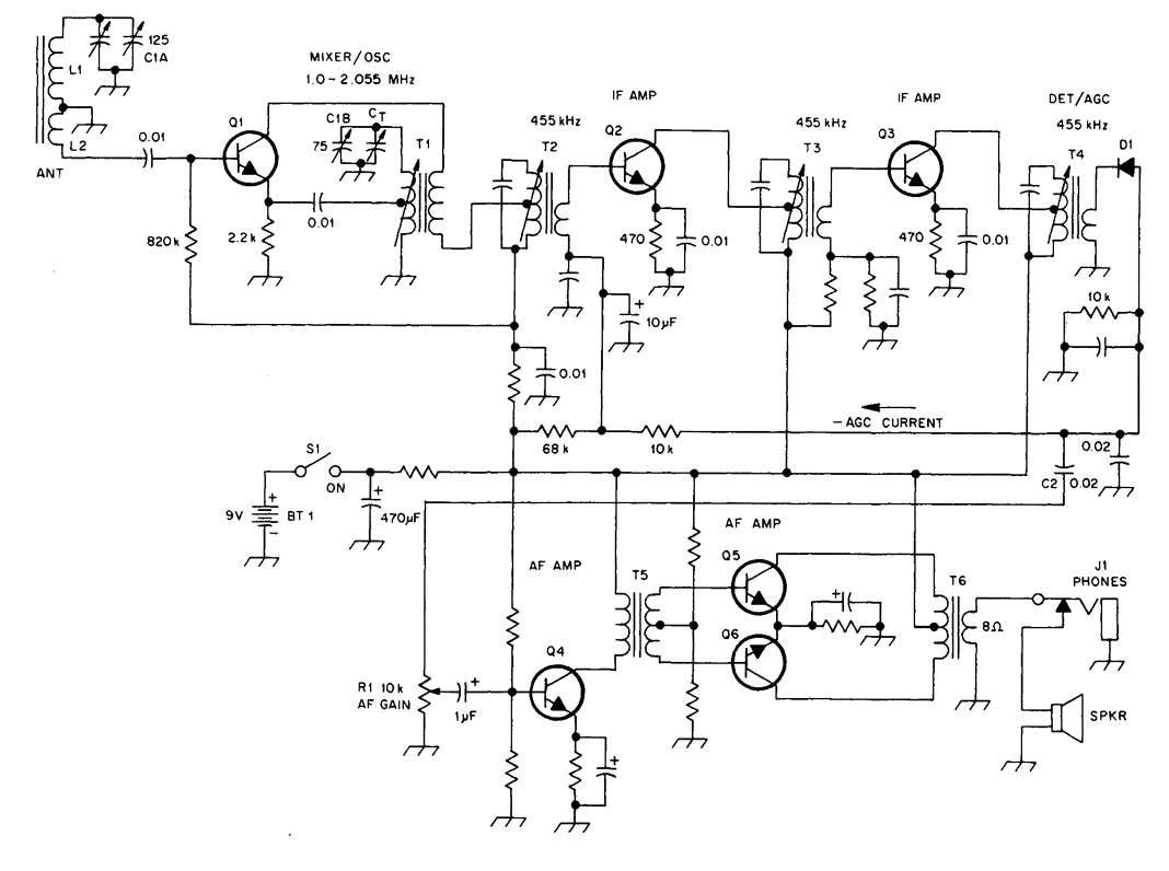
TRANSISTORIZED AM RADIO
The schematic illustrates a standard AM radio circuit utilizing NPN transistors. This generic circuit does not provide specific values for all components, serving instead as a reference point for experimenters to begin their projects.
The schematic of a typical transistor AM...
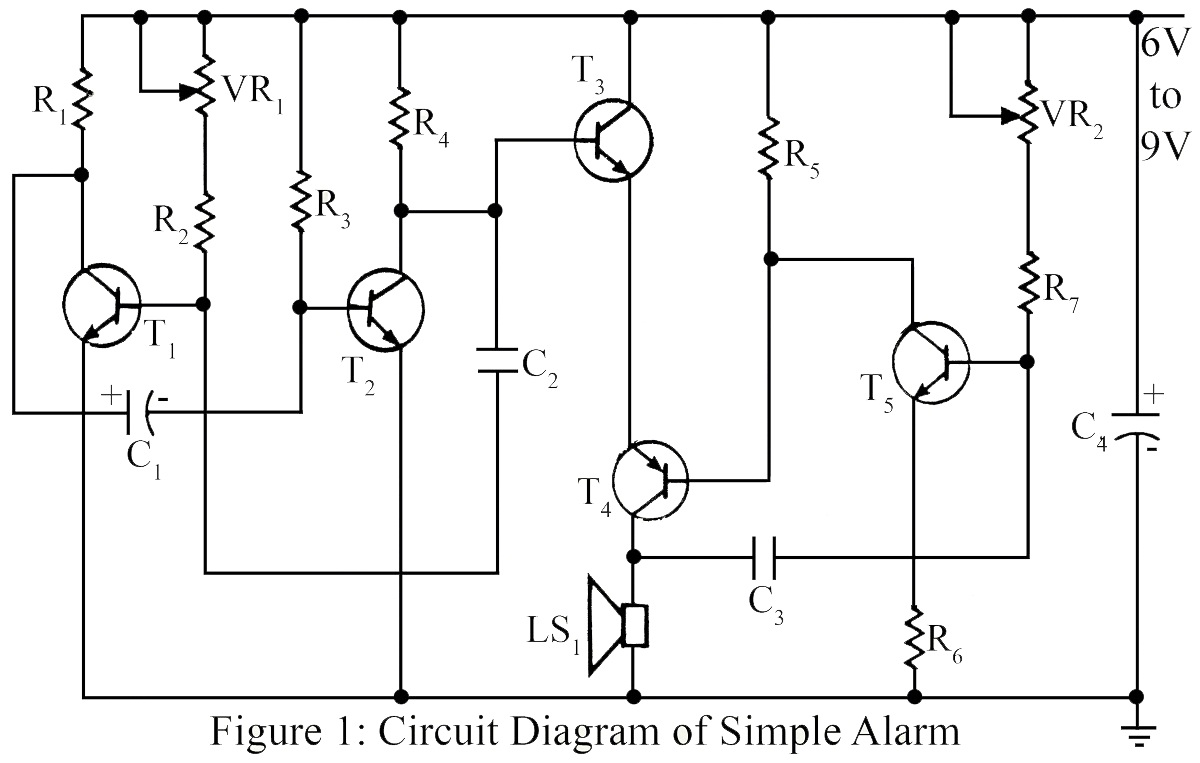
Simple Alarm Circuit
The simple circuit generates an audible alarm notification, functioning as a burglar alarm utilizing five transistors.
This circuit operates as a basic burglar alarm system designed to emit an audible sound when triggered. The core component of the circuit is a...
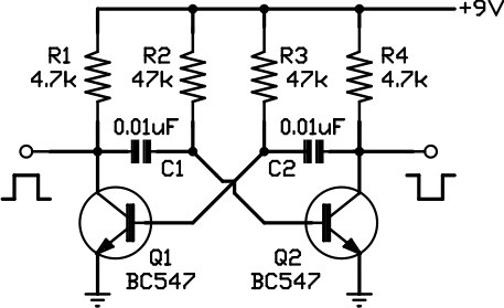
Two-phase squarewave oscillator
This circuit is one of the simplest to implement but can be challenging to comprehend. It consists of a two-transistor oscillator known as an astable multivibrator, which generates a square wave output that is out of phase. Initially, it is...

Transistor Circuits Design
Transistors are essential components of electronic circuits. The success of a circuit design depends on the selection of the appropriate transistor type and the calculations involved.
Transistors serve as fundamental building blocks in electronic circuits, playing critical roles in amplification, switching,...
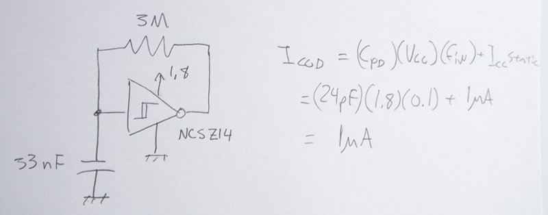
transistors Low power low voltage slow (0.1Hz) oscillator
The power supply varies, and the circuit must operate at under 10 µA of current (excluding the capacitor charging). It triggers a Silicon Controlled Rectifier (SCR) every 10 to 30 seconds as long as the power supply is above 1.8...

Single-junction transistor a phase-shift trigger circuit
Figure 16-29 (a) illustrates the trigger output through a resistor R2, while Figure 16-29 (b) depicts the integration of a programmable unidirectional transistor (PUT) trigger circuit. The adjustable potentiometer RP can modify the conduction angle of the TRIAC to facilitate...
metal detector circuit
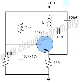
This project involves a simple metal detector circuit that is easy to construct using a single transistor and a few additional components. The circuit operates as a Colpitts oscillator, broadcasting on the AM band. To use it, place a quality...
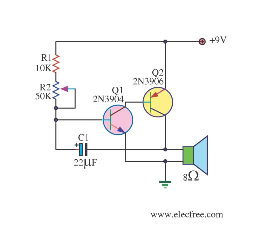
Simple Metronome using transistor
This circuit is a simple metronome model designed for ease of use. It employs transistors as key components, specifically configured as an astable multivibrator, to produce a beeping sound. The tone can be adjusted using a variable resistor (VR1). A...