


amplifier How does this circuit attenuate high frequencies
#treble control
#high pass filter
#low pass filter
#frequency attenuation
#gain control
#audio filter
#resistor network
#frequency response
#signal processing
#RC filter
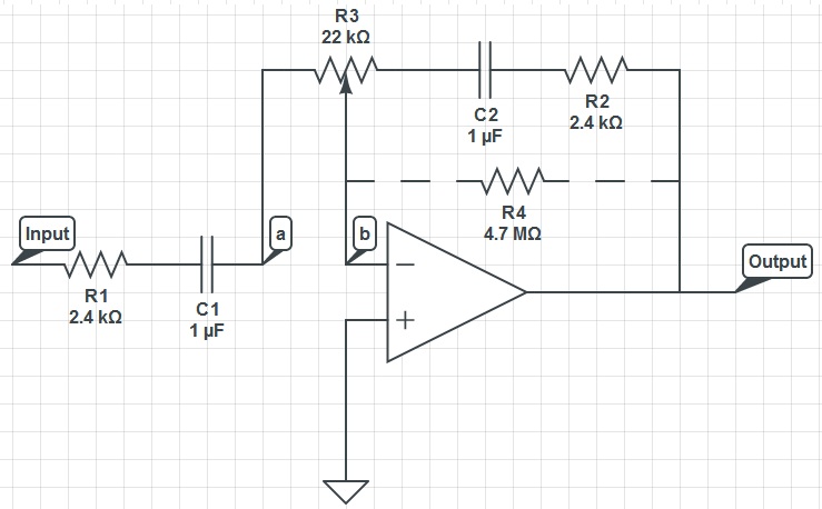
Description: This circuit can function as a treble control circuit, with high-frequency gain occurring when resistor R3 is set to a value that makes points a and b equal (denoted as k=0). Conversely, high-frequency attenuation occurs when R3 is set to 22 kOhms across points a and b (denoted as k=1). Therefore, depending on the setting of R3, this circuit operates either as a high-pass filter (k=0) or a low-pass filter (k=1).
The feedback mechanism in this circuit is crucial for understanding its operation. Capacitor C2 consistently presents a lower impedance at high frequencies, suggesting that adjusting R3 should primarily influence the gain at these frequencies. The role of feedback in amplifiers is essential, particularly in maintaining stability and controlling voltage fluctuations between the virtual ground input nodes. The circuit utilizes DC feedback to counteract any variations in voltage at the inputs by outputting a signal with a DC offset that is opposite to that at the inputs. While AC feedback can pass through a capacitor, it behaves like an open circuit for DC signals.
This circuit can be designed with the following components and configurations:
1. **Resistors**: R3 is the variable resistor that determines the circuit's behavior as either a high-pass or low-pass filter. The resistance value is critical, as it dictates the frequency response of the circuit.
2. **Capacitor**: C2 is a capacitor that influences the impedance characteristics of the circuit. Its lower impedance at higher frequencies allows for the desired filtering action.
3. **Amplifier**: An operational amplifier (op-amp) can be used to amplify the signal. The configuration of the feedback loop (including the resistors and capacitor) around the op-amp is essential for achieving the desired frequency response.
4. **Power Supply**: The circuit requires a stable DC power supply to operate the op-amp, ensuring consistent performance.
The circuit's performance can be analyzed using Bode plots to visualize the gain and phase shift across different frequencies. The transition between the high-pass and low-pass behavior is determined by the cutoff frequency, which can be calculated based on the values of R3 and C2.
In summary, this treble control circuit exemplifies the principles of feedback in amplifiers and the significance of component values in determining the overall frequency response. Proper understanding of these elements is crucial for effectively utilizing and modifying the circuit for various audio applications.This circuit could be used as a treble control circuit with high frequency gain occuring when R3 is set so a=b (we`ll call this k=0), and high frequency attenuation occuring when R3 is 22kOhms across a and b (k=1). So therefore, depending on R3`s setting, this circuit is either a high pass (k=0) or low pass (k=1) filter.
When comparing this circuit to high and low pass filters, I do not understand what is happening: C2 will always have a lower impedance for high frequencies and so surely adjusting R3 will only alter positive gain for high frequencies. It`s not a duplicate, but you are trying to understand this circuit without having clear what the simgle parts do.
Did you understand how the feedback works for an amplifier clabacchio™ May 16 `12 at 9:44 @clabacchio Yes, I think so. I understand that DC feedback is needed to control any fluctuations in voltage between the virtual ground input nodes to the amplifier.
It does this by outputing the signal with a DC offset opposite to that at the inputs. Although AC feedback can travel over a capacitor, for any DC signal it acts like an open circuit. user1083734 May 16 `12 at 9:50 I am a beginner but am finding all of the answers I have recieved on electronics. I realise the power of this resourse and certainly do not want to waste anybody`s time user1083734 May 16 `12 at 9:52 It`s not about that: you have to understand that DC feedback and AC feedback are, in principle, feedbacks.
From your first comment I see some confusion, and I don`t blame you :) but you should take things a bit more step by step. I`ve also edited my answer to give a bit more general notions, check it. clabacchio™ May 16 `12 at 10:00
The feedback mechanism in this circuit is crucial for understanding its operation. Capacitor C2 consistently presents a lower impedance at high frequencies, suggesting that adjusting R3 should primarily influence the gain at these frequencies. The role of feedback in amplifiers is essential, particularly in maintaining stability and controlling voltage fluctuations between the virtual ground input nodes. The circuit utilizes DC feedback to counteract any variations in voltage at the inputs by outputting a signal with a DC offset that is opposite to that at the inputs. While AC feedback can pass through a capacitor, it behaves like an open circuit for DC signals.
This circuit can be designed with the following components and configurations:
1. **Resistors**: R3 is the variable resistor that determines the circuit's behavior as either a high-pass or low-pass filter. The resistance value is critical, as it dictates the frequency response of the circuit.
2. **Capacitor**: C2 is a capacitor that influences the impedance characteristics of the circuit. Its lower impedance at higher frequencies allows for the desired filtering action.
3. **Amplifier**: An operational amplifier (op-amp) can be used to amplify the signal. The configuration of the feedback loop (including the resistors and capacitor) around the op-amp is essential for achieving the desired frequency response.
4. **Power Supply**: The circuit requires a stable DC power supply to operate the op-amp, ensuring consistent performance.
The circuit's performance can be analyzed using Bode plots to visualize the gain and phase shift across different frequencies. The transition between the high-pass and low-pass behavior is determined by the cutoff frequency, which can be calculated based on the values of R3 and C2.
In summary, this treble control circuit exemplifies the principles of feedback in amplifiers and the significance of component values in determining the overall frequency response. Proper understanding of these elements is crucial for effectively utilizing and modifying the circuit for various audio applications.This circuit could be used as a treble control circuit with high frequency gain occuring when R3 is set so a=b (we`ll call this k=0), and high frequency attenuation occuring when R3 is 22kOhms across a and b (k=1). So therefore, depending on R3`s setting, this circuit is either a high pass (k=0) or low pass (k=1) filter.
When comparing this circuit to high and low pass filters, I do not understand what is happening: C2 will always have a lower impedance for high frequencies and so surely adjusting R3 will only alter positive gain for high frequencies. It`s not a duplicate, but you are trying to understand this circuit without having clear what the simgle parts do.
Did you understand how the feedback works for an amplifier clabacchio™ May 16 `12 at 9:44 @clabacchio Yes, I think so. I understand that DC feedback is needed to control any fluctuations in voltage between the virtual ground input nodes to the amplifier.
It does this by outputing the signal with a DC offset opposite to that at the inputs. Although AC feedback can travel over a capacitor, for any DC signal it acts like an open circuit. user1083734 May 16 `12 at 9:50 I am a beginner but am finding all of the answers I have recieved on electronics. I realise the power of this resourse and certainly do not want to waste anybody`s time user1083734 May 16 `12 at 9:52 It`s not about that: you have to understand that DC feedback and AC feedback are, in principle, feedbacks.
From your first comment I see some confusion, and I don`t blame you :) but you should take things a bit more step by step. I`ve also edited my answer to give a bit more general notions, check it. clabacchio™ May 16 `12 at 10:00
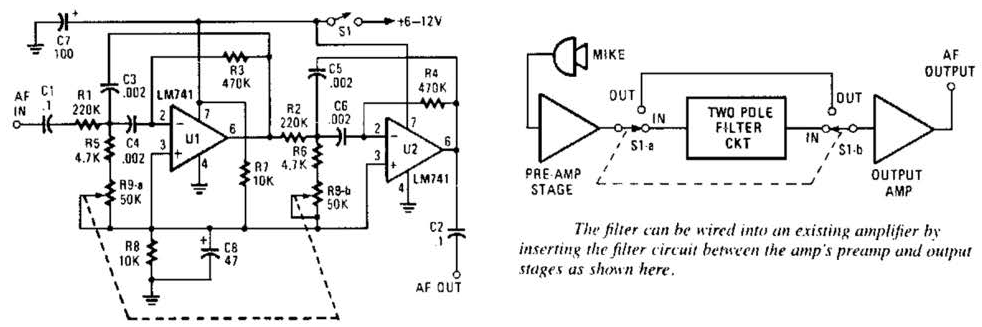
Build a Variable-Frequency Audio Band pass FilterCircuit
This variable-frequency audio bandpass filter is constructed using two 741 operational amplifiers connected in cascade. The two 741 op amps are configured as identical RC active filters and are cascaded to enhance selectivity. The filter's tuning range spans from 500...
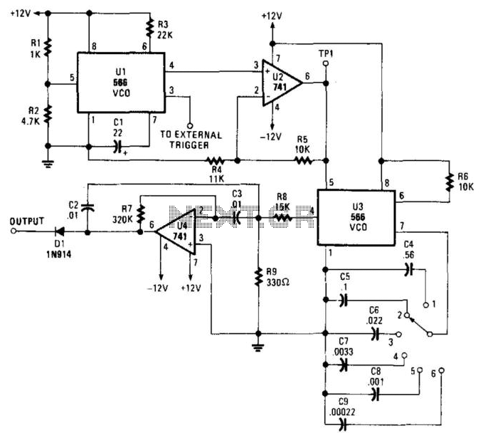
Audio Filter Analyzer
When this circuit is connected to a filter and an oscilloscope, the oscilloscope displays the filter's frequency response. A frequency that sweeps from low to high is applied to a filter. An oscilloscope is triggered by the start of the...

Nescaf mod
The NESCAF audio filter is a compact and cost-effective circuit that enhances amateur radio setups. It is particularly beneficial for radio receivers or transceivers that do not include an optional CW filter. However, one limitation of this filter is the...
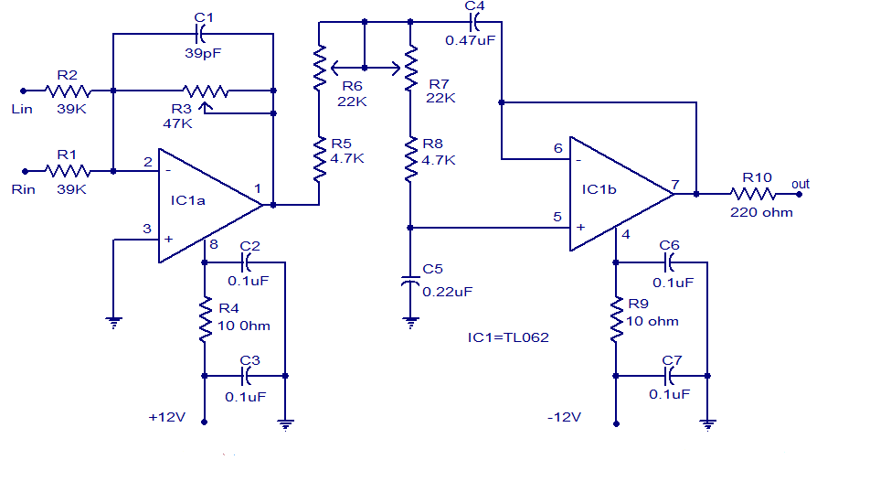
Filter
Several low-pass filter circuits for subwoofers are presented here, including this particular design. The circuit utilizes the TL062 operational amplifier from ST Microelectronics. The TL062 is a dual high-input impedance J-FET operational amplifier that features low power consumption and a...
gcr
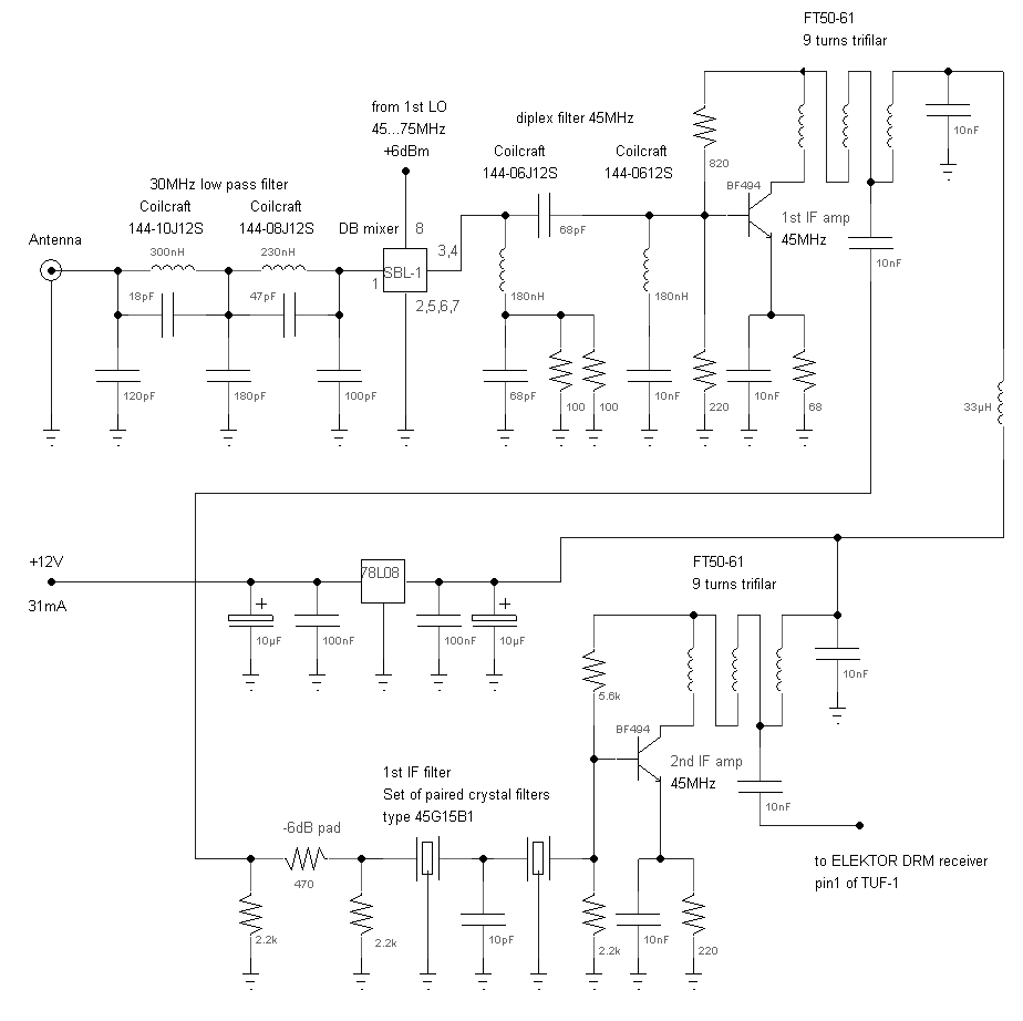
A 5-pole elliptic low pass filter (impedance: 50 Ohm, -6 dB cutoff frequency 33 MHz) connects the antenna signal to the diode ring mixer, a traditional SBL-1, which performs well even below 500 kHz. A high pass/low pass diplexing filter...
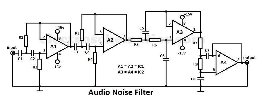
Audio Noise Filter Circuit
This audio noise filter circuit is a bandpass filter designed for the audio frequency range. It effectively filters out unwanted signals that fall below or above the audio frequency spectrum.
The audio noise filter circuit operates as a bandpass filter, which...
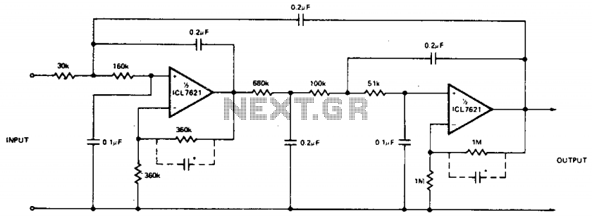
Multiple feedback low pass filter
The low bias currents allow for the utilization of high resistance and low capacitance values, facilitating a low frequency cutoff at fc = 10 Hz, with an AVCL of 4 and a passband ripple of 0.1 dB. Additionally, small capacitors...

LOW PASS WITH 10 kHz CUTOFF
The next throttle is a prototype assembled for testing purposes. It represents a modification of the basic transistor throttle. The SPDT switch enables the throttle to deliver either full or half-wave DC output. The value of the 8 µF capacitors...
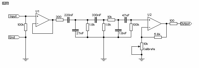
Filter For Audio Measurements
The purpose is supposedly to account for the fact that human hearing is less sensitive at low and high frequencies than in the upper midrange, and that this variation is dependent upon the sound intensity (SPL). The Fletcher-Munson curve (as...