


Available voltage booster 400Vp-p output
#voltage booster
#high voltage
#transistor
#OP amplifier
#power-driven
#floating voltage
#400Vp-p
#circuit design
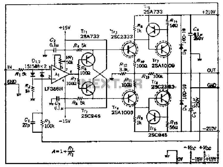
Description: This amplifier circuit operates with an OP amplifier that is power-driven, which leads to the presence of floating voltage errors and necessitates a high-pressure booster for transistor protection. The circuit utilizes a mutual feedback configuration, connecting to the output circuit in a reasonable manner without home bias and incorporating a water compensation circuit. High-voltage transistors are employed to facilitate the transfer of high voltage, utilizing a push-pull mode. The design aims to maintain the static pressure close to the supply voltage, with output transistors configured to ground the circuit. A two-stage DC-coupled circuit is implemented due to the significant voltage gain, necessitating negative feedback in the output stage. The closed-loop gain is designed to enhance performance, and a small resistance is included in the power amplifier circuit to prevent damage to the output transistors during negative short-circuit conditions. A protective circuit is integrated to limit current, ensuring safety and reliability. The current limit is set at approximately 10 mA, and diodes are employed to clamp and absorb ripple voltage generated in the circuit.
This amplifier circuit is designed to operate efficiently while addressing potential issues associated with floating voltage errors. The use of an operational amplifier (OP) ensures that the circuit can maintain its functionality under varying conditions. The high-pressure booster serves to stabilize the voltage levels, protecting the transistors from damage due to fluctuations.
The mutual feedback configuration enhances signal integrity by allowing for better control over the output circuit. The absence of home bias and the inclusion of a water compensation circuit contribute to the overall stability of the amplifier. The push-pull configuration of the high-voltage transistors ensures that both halves of the waveform are amplified effectively, leading to improved output performance.
The two-stage DC-coupled circuit is a critical aspect of the design, as it allows for significant voltage gain while minimizing distortion. The negative feedback applied in the output stage helps to maintain linearity and stability, which is essential for high-fidelity audio applications.
The inclusion of a small resistance in the power amplifier circuit serves as a precautionary measure against short-circuit conditions. In cases where a negative short-circuit current occurs, the protective circuit activates to limit the current, preventing damage to the output transistors. This current limit is carefully calibrated to approximately 10 mA, ensuring that the circuit remains within safe operating conditions.
Diodes are strategically placed within the circuit to absorb any ripple voltage generated during operation. These diodes perform a clamping function, ensuring that any excess voltage does not interfere with the circuit's performance. Overall, this amplifier circuit is designed with a focus on reliability, safety, and high performance, making it suitable for a variety of applications. Because this amplifier circuit OP mountain with isv power-driven, so sad existence as floating voltage error plus high pressure booster as a disc insurance o transistor Tri, TT J is mutual bashing shot summarized follower, this will be connected to the output circuit It would be more reasonable (no home bias, still water compensation circuit). High voltage transistor Tt, Tr to complete the transfer of a high voltage, in order to raise high soil line, and Used the push-pull mode.
To learn Cantonese peak locust static pressure as much as possible close to the supply voltage, the output transistor T ,. Ding, Trrb then lied shot Terrier ground circuit., By the Tr. Tr, (Tr4. Tr8) DC-coupled two-stage circuit, because the voltage gain is large, so the output stage negative feedback.
Closed-loop magnification static milli Guangdong times ( r F iso lI/z four soil), is to encourage the greater use OP. Ran lose 1 small resistance of power amplifier circuit, when there is a negative short-circuit current cut Luk frog, the output transistor is damaged, and therefore, we need to take to protect streams, Tr5, 1 prison..
Hang from the Qing limit the role of the protective circuit. Luk limit current IL Wang dish can be thrown -l V. 1. Workers, r amount./Island formula is obtained. Possession of the current limit circuit is about lOmA. Connected to the output terminal and Chrysler to good electrical ov lim of the diode D ugly, D play a clamping action to absorb the ripple voltage profile tallow produced.
This amplifier circuit is designed to operate efficiently while addressing potential issues associated with floating voltage errors. The use of an operational amplifier (OP) ensures that the circuit can maintain its functionality under varying conditions. The high-pressure booster serves to stabilize the voltage levels, protecting the transistors from damage due to fluctuations.
The mutual feedback configuration enhances signal integrity by allowing for better control over the output circuit. The absence of home bias and the inclusion of a water compensation circuit contribute to the overall stability of the amplifier. The push-pull configuration of the high-voltage transistors ensures that both halves of the waveform are amplified effectively, leading to improved output performance.
The two-stage DC-coupled circuit is a critical aspect of the design, as it allows for significant voltage gain while minimizing distortion. The negative feedback applied in the output stage helps to maintain linearity and stability, which is essential for high-fidelity audio applications.
The inclusion of a small resistance in the power amplifier circuit serves as a precautionary measure against short-circuit conditions. In cases where a negative short-circuit current occurs, the protective circuit activates to limit the current, preventing damage to the output transistors. This current limit is carefully calibrated to approximately 10 mA, ensuring that the circuit remains within safe operating conditions.
Diodes are strategically placed within the circuit to absorb any ripple voltage generated during operation. These diodes perform a clamping function, ensuring that any excess voltage does not interfere with the circuit's performance. Overall, this amplifier circuit is designed with a focus on reliability, safety, and high performance, making it suitable for a variety of applications. Because this amplifier circuit OP mountain with isv power-driven, so sad existence as floating voltage error plus high pressure booster as a disc insurance o transistor Tri, TT J is mutual bashing shot summarized follower, this will be connected to the output circuit It would be more reasonable (no home bias, still water compensation circuit). High voltage transistor Tt, Tr to complete the transfer of a high voltage, in order to raise high soil line, and Used the push-pull mode.
To learn Cantonese peak locust static pressure as much as possible close to the supply voltage, the output transistor T ,. Ding, Trrb then lied shot Terrier ground circuit., By the Tr. Tr, (Tr4. Tr8) DC-coupled two-stage circuit, because the voltage gain is large, so the output stage negative feedback.
Closed-loop magnification static milli Guangdong times ( r F iso lI/z four soil), is to encourage the greater use OP. Ran lose 1 small resistance of power amplifier circuit, when there is a negative short-circuit current cut Luk frog, the output transistor is damaged, and therefore, we need to take to protect streams, Tr5, 1 prison..
Hang from the Qing limit the role of the protective circuit. Luk limit current IL Wang dish can be thrown -l V. 1. Workers, r amount./Island formula is obtained. Possession of the current limit circuit is about lOmA. Connected to the output terminal and Chrysler to good electrical ov lim of the diode D ugly, D play a clamping action to absorb the ripple voltage profile tallow produced.
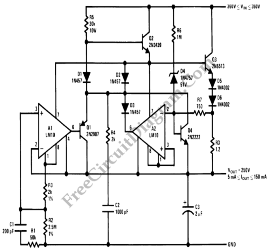
Foldback Current Limited High Voltage Regulator
This circuit is a high voltage regulator that features foldback current limiter protection. It utilizes the LM10 comparator along with a voltage reference in its core design.
The high voltage regulator circuit is designed to maintain a stable output voltage while...
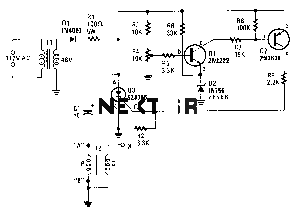
Capacitor-discharge-high-voltage-generator
A step-down transformer T1 reduces the incoming line voltage to approximately 48 Vac, which is then rectified by diode D1. The resulting direct current charges capacitor C1 through a current-limiting resistor R1 to a voltage level set by R4. When...

Transistor Circuits Design
Transistors are essential components of electronic circuits. The success of a circuit design depends on the selection of the appropriate transistor type and the calculations involved.
Transistors serve as fundamental building blocks in electronic circuits, playing critical roles in amplification, switching,...
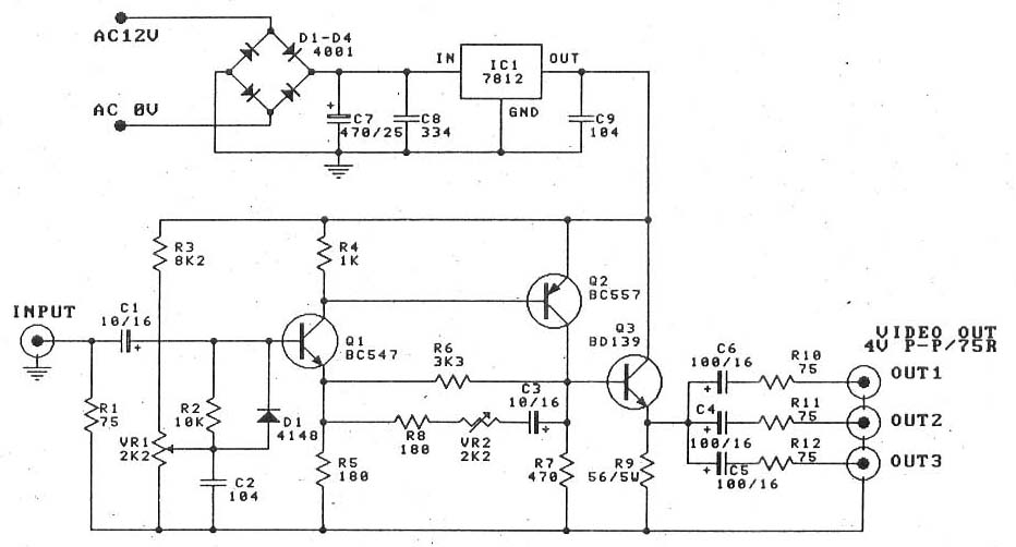
Video amplifier splitter by transistor BD137-BC547-BC557
This is a video amplifier circuit or video splitter circuit, designed to strengthen video signals. It compensates for signal loss and is...
The video amplifier circuit serves as a crucial component in video signal distribution systems, ensuring that the integrity and...
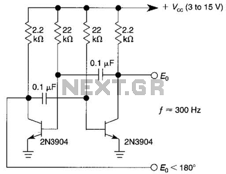
Astable Multivibrator Or Free-Running Square-Wave Oscillator Circuit
This free-running square-wave oscillator utilizes two NPN transistors. The output frequency is approximately 300 Hz with the specified component values.
The circuit operates as a basic oscillator, generating a square wave output through the interaction of two NPN transistors. The fundamental...
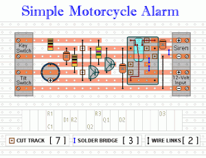
Easy Build Motorcycle Alarm
The following circuit is a simple, inexpensive, and easy-to-build motorcycle alarm. The circuit requires only two transistors to drive a relay, which acts as a switch to activate a buzzer. Any number of normally-open switches can be used. Mercury switches...
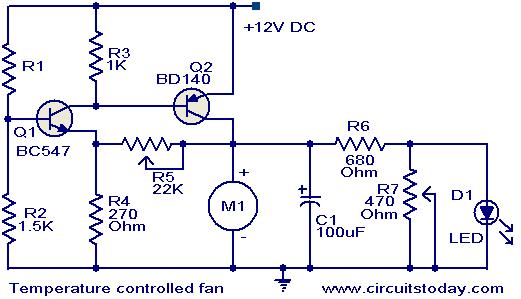
Temperature controlled DC fan
This circuit utilizes two transistors to regulate the speed of a 12 V DC fan based on temperature changes. A thermistor (R1) detects the temperature. As the temperature rises, the base current of transistor Q1 (BC 547) increases, leading to...
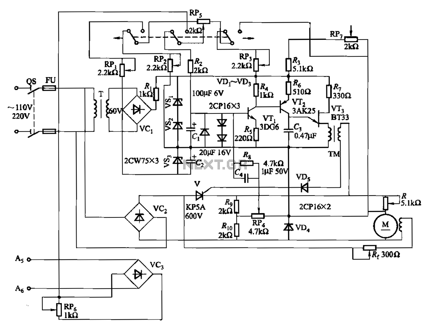
100W full-wave single-junction transistor trigger doer control circuit
A 100W full-wave single-junction transistor trigger control circuit designed for constant or variable speed control of a wire feed motor. The input control signal consists of a voltage adjusted by the master potentiometer (RPs) and a feedback voltage from potentiometer...
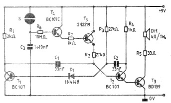
Simple Electronic bell circuit using transistors
A simple and practical electronic bell circuit can be constructed using the provided schematic diagram. This circuit can function as a doorbell or an alarm system. It utilizes only a few transistors along with several common components. The circuit is...