


Balance input with Gain
#gain regulation
#low noise
#symmetrical input
#microphone amplifier
#signal attenuation
#potentiometer
#IC
#low distortion
#audio signal
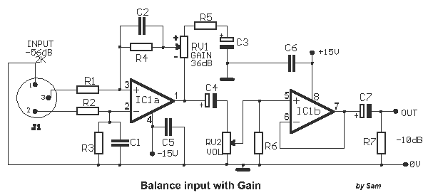
Description: Circuit with electronic symmetrical input, with possibility of regulation of the gain from the pontesometer RV1 and the level of signal with the RV2. The quality of pontesometer RV1 (as other material), should be very good, in order to we avoid annoying noises and voids in the regulation of gain. Beyond the types IC that I give, it can be used any other type, is enough it fills the characteristics that should, as low noise, distortion etc. With the prices of circuit, the input resistance are near in the 2KΩ, with result, it's suitable for amplification of low level of signal (Microphone). For higher level signals, it will be supposed it is used attenuation the signal, with resistances, and for the two input section, decreasing with this way, the regulation margins of gain, with the RV1.
The described circuit is an electronic amplifier designed for symmetrical input signals, making it suitable for applications such as microphone preamplification. The circuit features two adjustable potentiometers: RV1 for gain control and RV2 for signal level adjustment. The quality of these components is critical to minimizing noise and ensuring smooth regulation of gain. The use of high-quality potentiometers is essential to avoid undesirable artifacts in the audio signal.
The circuit employs operational amplifiers, specifically the NE5532 or TL072, which are known for their low noise and low distortion characteristics. These op-amps are suitable for audio applications, providing excellent performance in signal amplification tasks. The input resistance of approximately 2kΩ makes the circuit well-suited for low-level signals, such as those from microphones, while allowing for higher-level signals to be attenuated through appropriate resistive components.
The part list includes various resistors and capacitors that contribute to the circuit's performance. Resistors R1 and R2 are 2.2kΩ metal film with a tolerance of 1%, ensuring precision in the circuit's operation. Capacitors C1 and C2, rated at 68pF, are used for frequency stabilization, while C3 and C4, with values of 47µF and 10µF respectively, serve as coupling capacitors to block DC while allowing AC signals to pass. The potentiometers RV1 and RV2 are specified as logarithmic types, with values of 10kΩ and 47kΩ, respectively, to provide a more natural control over gain and signal levels.
The circuit also includes additional resistors (R3, R4, R5, R6, R7) and capacitors (C5, C6, C7) that are critical for setting the appropriate gain structure and filtering unwanted frequencies. The output is designed to connect to a standard female XLR (CANNON) plug, which is common in professional audio equipment, ensuring compatibility with various audio systems.
In summary, this circuit is a well-designed audio amplifier with adjustable gain and signal level controls, suitable for low-level audio signals and capable of handling higher-level signals through attenuation. The careful selection of components and their specifications contributes to the overall performance and reliability of the circuit in audio applications.Circuit with electronic symmetrical input, with possibility of regulation of the gain from the pontesometer RV1 and the level of signal with the RV2. The quality of pontesometer RV1 (as other material), should be very good, in order to we avoid annoying noises and voids in the regulation of gain.
Beyond the types IC that I give, it can be used any other type, is enough it fills the characteristics that should, as low noise, distortion etc. With the prices of circuit, the input resistance are near in the 2K?, with result, it's suitable for amplification of low level of signal (Microphone).
For higher level signals, it will be supposed it is used attenuation the signal, with resistances, and for the two input sect?on, decreasing with this way, the regulation margins of gain, with the RV1. Part List R1-2= 2.2Kohms metal film 1% C1-2= 68pF ceramic OR milar ICI= NE5532 -TL072 R3= 22Kohms metal film 1% C3= 47uF 25V RV1= 10Kohms Log. R4= 6.8Kohmsmetal film 1% C4= 10uF 25V RV2= 47Kohms Log. R5= 100ohms C5-6= 100nF100V cer. OR mkt J1= Female CANNON plug R6-7= 47Kohms C7= 10uF25V .
The described circuit is an electronic amplifier designed for symmetrical input signals, making it suitable for applications such as microphone preamplification. The circuit features two adjustable potentiometers: RV1 for gain control and RV2 for signal level adjustment. The quality of these components is critical to minimizing noise and ensuring smooth regulation of gain. The use of high-quality potentiometers is essential to avoid undesirable artifacts in the audio signal.
The circuit employs operational amplifiers, specifically the NE5532 or TL072, which are known for their low noise and low distortion characteristics. These op-amps are suitable for audio applications, providing excellent performance in signal amplification tasks. The input resistance of approximately 2kΩ makes the circuit well-suited for low-level signals, such as those from microphones, while allowing for higher-level signals to be attenuated through appropriate resistive components.
The part list includes various resistors and capacitors that contribute to the circuit's performance. Resistors R1 and R2 are 2.2kΩ metal film with a tolerance of 1%, ensuring precision in the circuit's operation. Capacitors C1 and C2, rated at 68pF, are used for frequency stabilization, while C3 and C4, with values of 47µF and 10µF respectively, serve as coupling capacitors to block DC while allowing AC signals to pass. The potentiometers RV1 and RV2 are specified as logarithmic types, with values of 10kΩ and 47kΩ, respectively, to provide a more natural control over gain and signal levels.
The circuit also includes additional resistors (R3, R4, R5, R6, R7) and capacitors (C5, C6, C7) that are critical for setting the appropriate gain structure and filtering unwanted frequencies. The output is designed to connect to a standard female XLR (CANNON) plug, which is common in professional audio equipment, ensuring compatibility with various audio systems.
In summary, this circuit is a well-designed audio amplifier with adjustable gain and signal level controls, suitable for low-level audio signals and capable of handling higher-level signals through attenuation. The careful selection of components and their specifications contributes to the overall performance and reliability of the circuit in audio applications.Circuit with electronic symmetrical input, with possibility of regulation of the gain from the pontesometer RV1 and the level of signal with the RV2. The quality of pontesometer RV1 (as other material), should be very good, in order to we avoid annoying noises and voids in the regulation of gain.
Beyond the types IC that I give, it can be used any other type, is enough it fills the characteristics that should, as low noise, distortion etc. With the prices of circuit, the input resistance are near in the 2K?, with result, it's suitable for amplification of low level of signal (Microphone).
For higher level signals, it will be supposed it is used attenuation the signal, with resistances, and for the two input sect?on, decreasing with this way, the regulation margins of gain, with the RV1. Part List R1-2= 2.2Kohms metal film 1% C1-2= 68pF ceramic OR milar ICI= NE5532 -TL072 R3= 22Kohms metal film 1% C3= 47uF 25V RV1= 10Kohms Log. R4= 6.8Kohmsmetal film 1% C4= 10uF 25V RV2= 47Kohms Log. R5= 100ohms C5-6= 100nF100V cer. OR mkt J1= Female CANNON plug R6-7= 47Kohms C7= 10uF25V .
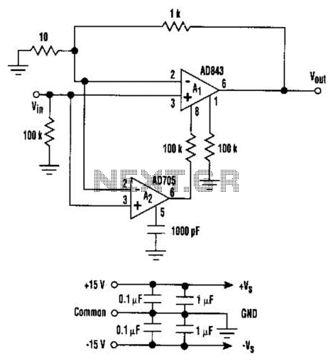
Low Noise And Drift Composite Amp Circuit
This circuit combines the advantages of low input offset voltage and drift without compromising the overall dynamic performance of the system. When compared to a standalone FET input operational amplifier, the composite amplifier circuit demonstrates a 20-fold improvement in voltage...
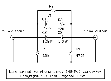
Line level to phono input
The circuit performs two functions: signal level attenuation and inverse RIAA filtering. Signal attenuation is required to convert a 500 mV signal to a 2.5 mV signal. Inverse-RIAA filtering is necessary to achieve a flat frequency response, similar to the...
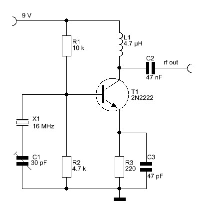
low noise oscillator design
The overall performance of any RF circuit regarding its phase noise and spectral purity depends significantly on the frequency-generating circuitry, commonly an oscillator. Low noise oscillators with high spectral purity are neither mysterious nor magical. Many individuals perceive the design...
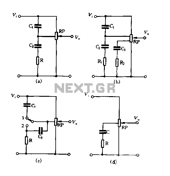
Using tap potentiometer loudness circuit
Figure 1.88 illustrates the loudness control circuit utilizing multiple taps on a potentiometer. In Figure (A), the connection is made between the tap and the potentiometer's input, along with the ground. An RC compensation network is employed, where the slide...
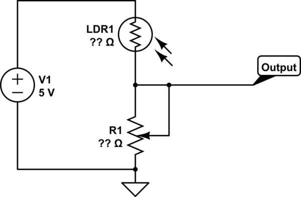
potentiometer Making an adjustable resistance
This part of the circuit is isolated from any other component, except for the 5V and ground connections. It includes LEDs and a shift register, which may not interact significantly. The LDR (Light Dependent Resistor) is utilized solely as a...
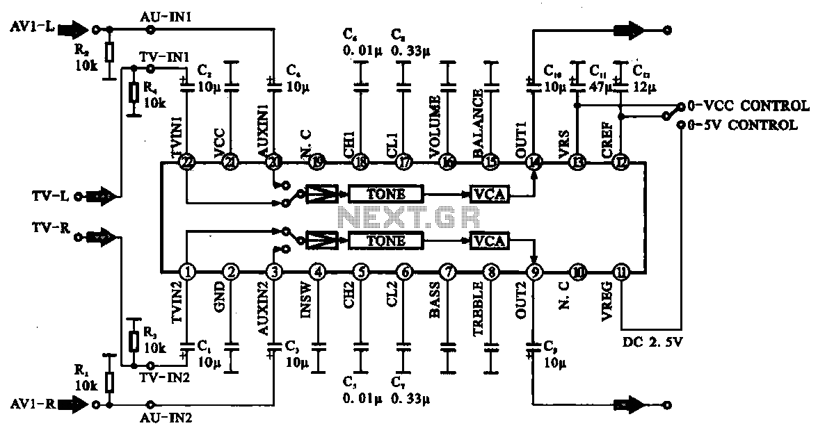
Audio signal control circuit
Audio signal control circuit. It illustrates a typical audio signal control circuit where two audio signals enter the integrated circuit through switching and tone controls (treble and bass), subsequently adjusting the output sent to the audio power amplifier.
The audio signal...
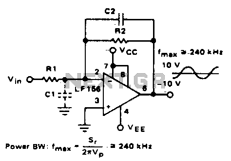
Wide bandwidth low noise amplifier
Parasitic input capacitance (ICi) is 3pF for LM5S, LF156, and LF157, along with any additional layout capacitance. This interacts with the feedback element and creates undesirable high-frequency effects. To mitigate this, a capacitor (C2) should be added in conjunction with...
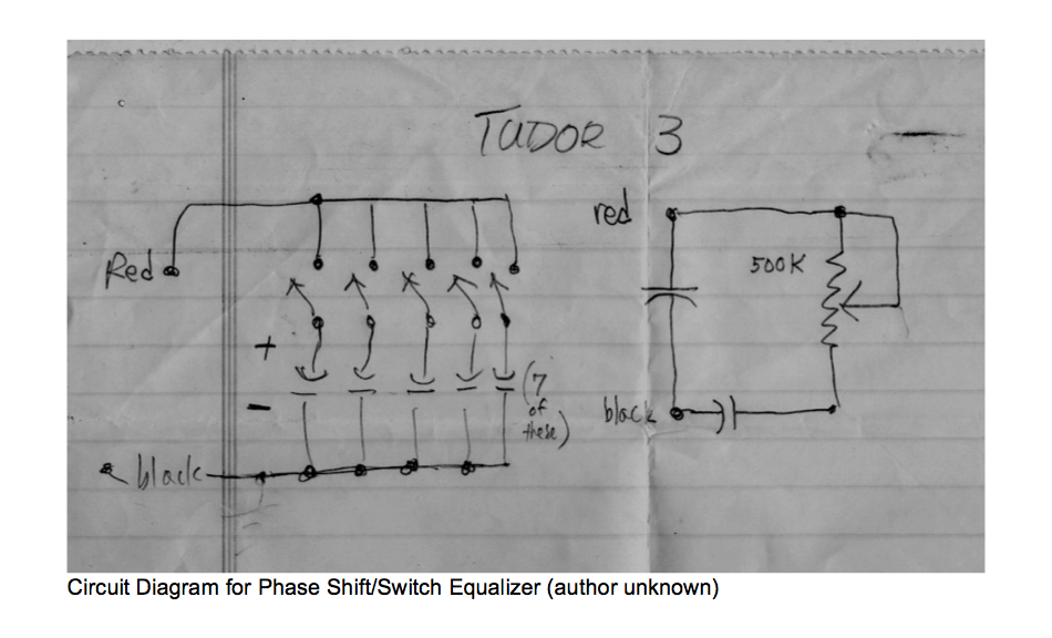
music circuit
This circuit allows for the adjustment of resistance using a potentiometer and the adjustment of capacitance by opening or closing switches. By manipulating the configuration of these switches, various combinations can be achieved to obtain different effective capacitance values. It...
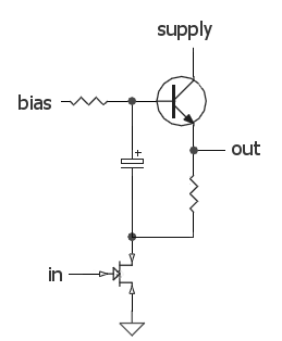
DC biasing audio signal
The audio source will be a line-level audio signal ranging from -2V to +2V AC, which will be passed through a 220µF coupling capacitor followed by a two-pole low-pass filter (RC). The signal will be processed by an Analog-to-Digital Converter...