


Boosters Are Not Buffers
#booster
#buffer
#impedance
#LPB1
#audio
#signal processing
#high input impedance
#low output impedance
#circuit design
#electronics
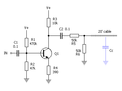
Description: Boosters are not buffers. While it is possible to design a booster that also functions as a buffer, most commercially available boosters, whether ready-made or in kits, lack the appropriate design to serve as buffers. A buffer should possess a high input impedance (Z) and a low output impedance. The LPB1, referenced at the beginning of this text, has a relatively low input impedance, disqualifying it from being categorized as a buffer. The mini-booster features a high input impedance but has a moderately high output impedance, making it unsuitable as a buffer as well. Another design aspect that hinders their functionality as buffers is the presence of a volume control potentiometer at the output. The volume potentiometer affects the circuit's impedance. When the volume potentiometer is set to the 50% position, as represented by R5 and R6, it acts as a voltage divider. In this case, the 100k potentiometer is in parallel with the output impedance of the LPB1 (10k), which drives the cable to the amplifier or the next pedal. The cable capacitance (Cc), even in high-quality cables, can measure around 800pF, as previously measured, and is depicted in light blue in the schematic. The output impedance of the booster and the resistance of the potentiometer drive the cable, forming a low-pass filter with the cable capacitance. Consequently, high frequencies begin to roll off starting at approximately 7.2kHz, which is not desirable for a buffer. This scenario is typical of an op-amp distortion pedal schematic fragment, where the high-frequency limit is comparable to that of a transistor booster example (with a 7.5kHz corner frequency). It is important to note that as the volume is increased, the frequency limit also rises, allowing more high frequencies to pass through. The shunt resistance of the potentiometer, represented as R6 in the examples, is in parallel with the input impedance of the subsequent stage. If that stage is a pedal with high impedance, much of the benefit of the high Z input will be negated since the resistance of the potentiometer is in parallel with the input, effectively lowering the impedance. This alteration impacts how a pedal responds to an input signal and varies with the volume potentiometer setting. These examples demonstrate that an unbuffered volume potentiometer at a pedal circuit output can pose issues, whether in a booster like the LPB1 or a distortion pedal like the Fuzzface (which uses a 500k potentiometer, exacerbating the problem). The AMZ Mosfet Booster serves as a good example of a booster design that lacks a volume control at its output, and its relatively low output impedance allows it to drive cables with minimal difficulty; the 2.7k output impedance can drive a 20 ft. cable at frequencies exceeding 73kHz.
The discussion of booster and buffer circuits highlights critical design considerations in audio electronics. Buffers are essential in maintaining signal integrity and preventing loading effects that can degrade audio quality. The characteristics of input and output impedance are crucial; a high input impedance ensures that the buffer does not load down the preceding stage, while a low output impedance allows it to drive the next stage effectively without significant signal loss.
In practical applications, the choice of components such as potentiometers and their configuration plays a vital role in the overall performance of a circuit. The use of a volume control potentiometer introduces complexities, particularly in terms of impedance interaction. The voltage divider effect of the potentiometer can lead to unintended frequency roll-off, particularly in high-frequency signals, which is detrimental in scenarios where clarity and fidelity are paramount.
Furthermore, the cable capacitance, which varies with cable quality and length, can significantly affect the frequency response of the circuit. Designers must account for this when designing circuits intended to drive long cable runs, ensuring that the output impedance is sufficiently low to mitigate the impact of cable capacitance on high-frequency performance.
In summary, understanding the differences between boosters and buffers, as well as their respective design requirements, is essential for achieving optimal performance in audio signal processing. The careful selection of components and circuit topology is necessary to ensure that the desired audio characteristics are preserved throughout the signal chain.Boosters are not buffers! While it is possible to make a booster that also provides a buffering action, the vast majority of the boosters commercially available ready-made or kits, do not have the proper design to be buffers. A buffer should have a high input impedance (Z) and a low output impedance. The LPB1, shown at the top of this post, has a fairly low input impedance, which automatically disqualifies it from the buffer category. The mini-booster has a high input impedance but a moderately high output Z, and is not a good buffer either. Another part of these designs that prevents their use as buffers is that they have a volume control potentiometer on the output.
The volume pot impacts the impedance of the circuit. If the volume pot is at the 50% position, represented above by R5 and R6, the output pot is acting as a voltage divider. Here we have the 100k pot in parallel with the output impedance of the LPB1 (10k) that is driving the cable to the amp or next pedal.
The cable capacitance (Cc) even on a good cable can be 800pF, as I measured in a previous test, and is shown on the schematic in light blue. The output impedance of the booster and the resistance of the pot are driving the cable and form a low pass filter with the cable capacitance.
In this example, the high frequencies are rolled off starting at around 7. 2kHz. This is obviously not what we want from a buffer! This is a typical opamp distortion pedal schematic fragment, and the high frequency limit is similar to the transistor booster example (7. 5kHz corner frequency). You should note that as the volume is turned up, the frequency limit rises as well, letting more high frequencies through.
The shunt resistance of the pot, shown as R6 on the examples, is in parallel with the input impedance of the next stage. If that stage is a pedal with a high impedance, much of the advantages of the high Z input will be lost since the resistance of the pot is in parallel with the input and effectively reduces the impedance.
This will change how a pedal responds or reacts to an input signal, and will vary with the setting of the volume pot. It is obvious from these examples that an unbuffered volume pot on a pedal circuit output can be a problem, whether on a booster like the LPB or a distortion pedal like the Fuzzface (which has a 500k pot that makes the problem even more noticeable).
The AMZ Mosfet Booster is a good example of a booster design that does not have a volume control on its output, and its fairly low output Z makes it capable of driving cables with little difficulty the 2. 7k output Z will drive the 20 ft. cable in our example to over 73kHz!
The discussion of booster and buffer circuits highlights critical design considerations in audio electronics. Buffers are essential in maintaining signal integrity and preventing loading effects that can degrade audio quality. The characteristics of input and output impedance are crucial; a high input impedance ensures that the buffer does not load down the preceding stage, while a low output impedance allows it to drive the next stage effectively without significant signal loss.
In practical applications, the choice of components such as potentiometers and their configuration plays a vital role in the overall performance of a circuit. The use of a volume control potentiometer introduces complexities, particularly in terms of impedance interaction. The voltage divider effect of the potentiometer can lead to unintended frequency roll-off, particularly in high-frequency signals, which is detrimental in scenarios where clarity and fidelity are paramount.
Furthermore, the cable capacitance, which varies with cable quality and length, can significantly affect the frequency response of the circuit. Designers must account for this when designing circuits intended to drive long cable runs, ensuring that the output impedance is sufficiently low to mitigate the impact of cable capacitance on high-frequency performance.
In summary, understanding the differences between boosters and buffers, as well as their respective design requirements, is essential for achieving optimal performance in audio signal processing. The careful selection of components and circuit topology is necessary to ensure that the desired audio characteristics are preserved throughout the signal chain.Boosters are not buffers! While it is possible to make a booster that also provides a buffering action, the vast majority of the boosters commercially available ready-made or kits, do not have the proper design to be buffers. A buffer should have a high input impedance (Z) and a low output impedance. The LPB1, shown at the top of this post, has a fairly low input impedance, which automatically disqualifies it from the buffer category. The mini-booster has a high input impedance but a moderately high output Z, and is not a good buffer either. Another part of these designs that prevents their use as buffers is that they have a volume control potentiometer on the output.
The volume pot impacts the impedance of the circuit. If the volume pot is at the 50% position, represented above by R5 and R6, the output pot is acting as a voltage divider. Here we have the 100k pot in parallel with the output impedance of the LPB1 (10k) that is driving the cable to the amp or next pedal.
The cable capacitance (Cc) even on a good cable can be 800pF, as I measured in a previous test, and is shown on the schematic in light blue. The output impedance of the booster and the resistance of the pot are driving the cable and form a low pass filter with the cable capacitance.
In this example, the high frequencies are rolled off starting at around 7. 2kHz. This is obviously not what we want from a buffer! This is a typical opamp distortion pedal schematic fragment, and the high frequency limit is similar to the transistor booster example (7. 5kHz corner frequency). You should note that as the volume is turned up, the frequency limit rises as well, letting more high frequencies through.
The shunt resistance of the pot, shown as R6 on the examples, is in parallel with the input impedance of the next stage. If that stage is a pedal with a high impedance, much of the advantages of the high Z input will be lost since the resistance of the pot is in parallel with the input and effectively reduces the impedance.
This will change how a pedal responds or reacts to an input signal, and will vary with the setting of the volume pot. It is obvious from these examples that an unbuffered volume pot on a pedal circuit output can be a problem, whether on a booster like the LPB or a distortion pedal like the Fuzzface (which has a 500k pot that makes the problem even more noticeable).
The AMZ Mosfet Booster is a good example of a booster design that does not have a volume control on its output, and its fairly low output Z makes it capable of driving cables with little difficulty the 2. 7k output Z will drive the 20 ft. cable in our example to over 73kHz!
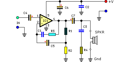
7 Watt Audio Power Amplifier Circuit Schematic
This compact amplifier is built around the TDA2003 integrated circuit, which can deliver 4W RMS at a 4-ohm load. The TDA2003 offers enhanced performance while maintaining the same pin configuration as the TDA2002. It retains the advantageous features of the...
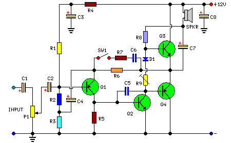
2Watt Audio Amplifier circuit
This amplifier is designed to be self-contained within a compact loudspeaker enclosure. It can be powered by devices such as Walkmans, Mini Discs, iPods, CD players, computers, and other devices equipped with line or headphone outputs. Typically, two units are...
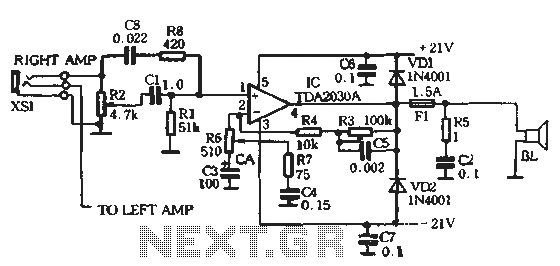
Dual 25W stereo audio power amplifier circuit
The circuit comprises two main components: the Lisheng power amplifier and the rectifier filter section. The stereo audio power amplifier circuit diagram, depicted in Figure 5-85, illustrates only one channel, with the other channel being identical. The audio signal is...
Audio/Video Switcher
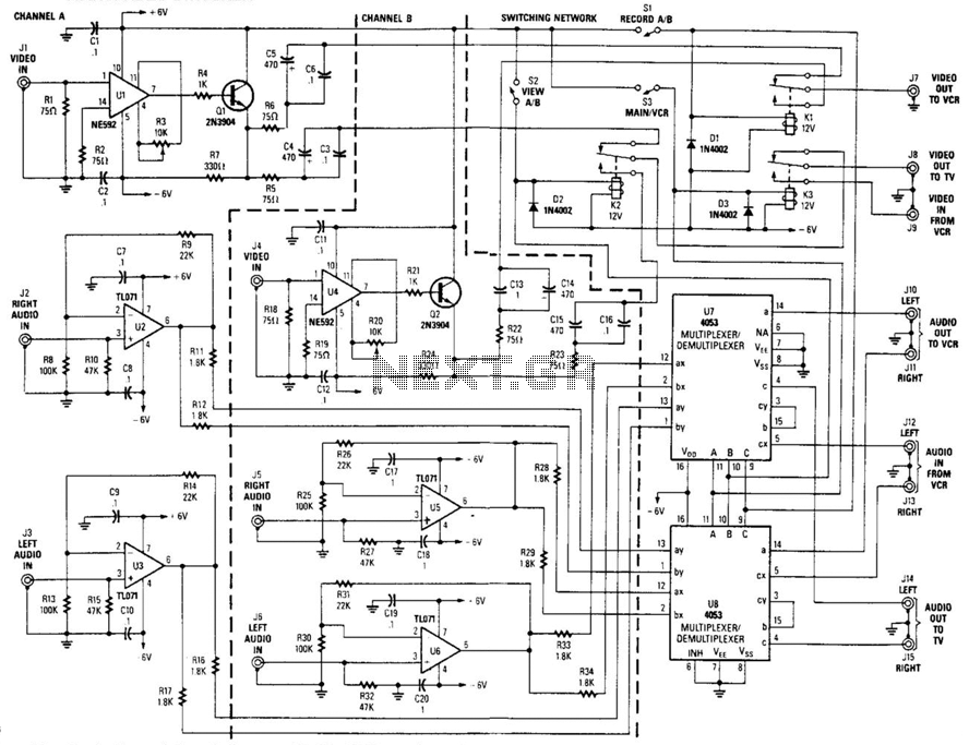
This circuit is a two-channel baseband video switcher. Buffer amplifiers U1/Q1, U4/Q4, and associated components produce a buffered 75-ohm video signal, which is routed to the switching network K1/K2/K3. Relay K1 selects either of the two video amplifiers and feeds...
Small Discrete Audio Power Amplifier
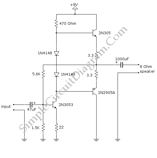
This is a small audio amplifier, similar to those used in small transistor radios. The circuit draws approximately 30 milliamps from a 9-volt supply and consists of two stages. The first stage is the input stage using a 2N3053 transistor,...
Audio Booster
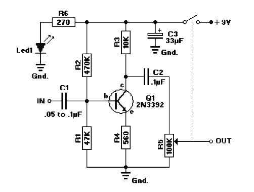
The circuit diagram represents a booster for an audio application. It features a linear potentiometer R5 with a resistance of 100K ohms, which includes an on/off switch. The capacitor C1 should be selected with a value between 0.05 µF and...
RC Audio Oscillator
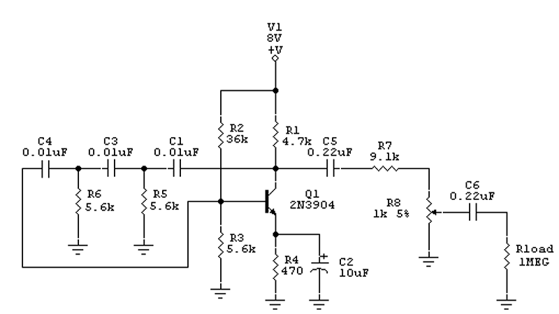
This document presents the design of an audio oscillator that operates at approximately 1 kHz. The circuit is likely sourced from EMFRD, as Wes's book contains a wealth of valuable circuits. This versatile oscillator serves as a signal source for...

Simple Hybrid Audio Amplifier
The ongoing debate regarding the superiority of valves versus transistors is not the focus here. However, for those undecided, this simple amplifier serves as an excellent test. It employs a valve as a pre-amplifier and a MOSFET in the output...
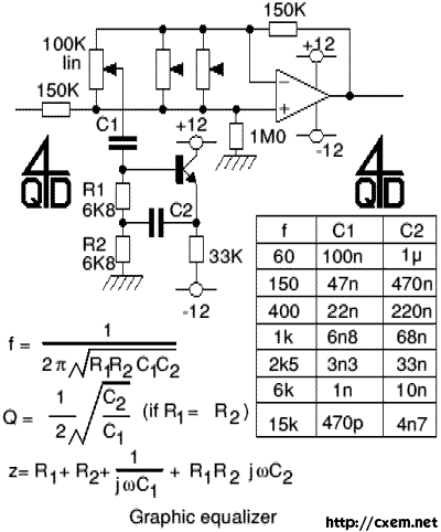
Audio Graphic Equaliser
Audio Graphic Equalizer. Audio graphic equalizers are widely used as commercial products in high-fidelity systems, car audio, and stage applications; however, circuits for these devices are seldom published.
Audio graphic equalizers are essential tools in audio processing, allowing users to adjust...