


Common collector amplifier circuit DC and AC path b
#common collector
#transistor
#amplifier circuit
#DC path
#AC path
#signal amplification
#bipolar junction transistor
#emitter follower
#analog circuit
#electronics
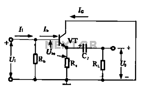
Description: A common collector amplifier circuit can be analyzed through its DC and AC paths. The DC path provides a bias circuit for the power transistor, determining whether it is in an active or off state, primarily influenced by the biasing. This circuit also supplies energy to the transistor. The AC signal path functions by treating the AC signal capacitor as a short circuit, with the internal resistance of the power supply also being influenced by this short-circuiting of the AC signal.
The common collector amplifier, also known as an emitter follower, is a configuration that provides voltage gain while maintaining a low output impedance. It is particularly useful for impedance matching between different stages of a circuit. The circuit comprises a bipolar junction transistor (BJT) with its collector connected to the power supply and the emitter connected to the load. The input signal is applied to the base of the transistor.
In the DC analysis, the biasing network is crucial for the proper operation of the amplifier. Typically, resistors are used to set the base voltage, ensuring that the transistor operates in the active region. The DC path allows for the establishment of a stable operating point, which is essential for linear amplification. The bias current flowing through the transistor is determined by the values of the resistors in the biasing network and the power supply voltage.
For AC analysis, the circuit's behavior is examined under small-signal conditions. The coupling capacitor, connected at the input, blocks any DC component of the signal while allowing AC signals to pass. This capacitor effectively shorts the AC signal to ground at higher frequencies, ensuring that the transistor responds only to the variations in the input signal. The output voltage follows the input voltage, minus the base-emitter voltage drop, which is typically around 0.7V for silicon transistors.
In summary, the common collector amplifier is an essential building block in analog electronics, providing efficient signal buffering and impedance transformation. Its design considerations, including biasing and coupling, are critical for achieving the desired performance in various applications. Common collector amplifier circuit DC and AC path b (3) common-collector amplifier circuit DC and AC path when common collector amplifier circuit for analysis, can be divided i nto DC and AC two paths, as shown in FIG. The DC path to provide a DC bias circuit of the circuit from the power transistor, the transistor is in an enlarged state or the off state, it is mainly determined by the bias. This circuit also provides energy for the transistor circuit. AC AC signal path is functioning circuit, a capacitor AC signal can be regarded as a short circuit, the internal resistance of the power supply also depends on the AC signal is short-circuited.
The common collector amplifier, also known as an emitter follower, is a configuration that provides voltage gain while maintaining a low output impedance. It is particularly useful for impedance matching between different stages of a circuit. The circuit comprises a bipolar junction transistor (BJT) with its collector connected to the power supply and the emitter connected to the load. The input signal is applied to the base of the transistor.
In the DC analysis, the biasing network is crucial for the proper operation of the amplifier. Typically, resistors are used to set the base voltage, ensuring that the transistor operates in the active region. The DC path allows for the establishment of a stable operating point, which is essential for linear amplification. The bias current flowing through the transistor is determined by the values of the resistors in the biasing network and the power supply voltage.
For AC analysis, the circuit's behavior is examined under small-signal conditions. The coupling capacitor, connected at the input, blocks any DC component of the signal while allowing AC signals to pass. This capacitor effectively shorts the AC signal to ground at higher frequencies, ensuring that the transistor responds only to the variations in the input signal. The output voltage follows the input voltage, minus the base-emitter voltage drop, which is typically around 0.7V for silicon transistors.
In summary, the common collector amplifier is an essential building block in analog electronics, providing efficient signal buffering and impedance transformation. Its design considerations, including biasing and coupling, are critical for achieving the desired performance in various applications. Common collector amplifier circuit DC and AC path b (3) common-collector amplifier circuit DC and AC path when common collector amplifier circuit for analysis, can be divided i nto DC and AC two paths, as shown in FIG. The DC path to provide a DC bias circuit of the circuit from the power transistor, the transistor is in an enlarged state or the off state, it is mainly determined by the bias. This circuit also provides energy for the transistor circuit. AC AC signal path is functioning circuit, a capacitor AC signal can be regarded as a short circuit, the internal resistance of the power supply also depends on the AC signal is short-circuited.
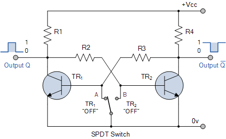
Transistor Bistable Multivibrator or Flip-flop
Electronics tutorial about bistable multivibrator, also known as the bistable flip-flop or two-shot multivibrator, constructed from transistors or logic gates.
A bistable multivibrator is a fundamental electronic circuit that has two stable states and can maintain its state indefinitely until triggered...
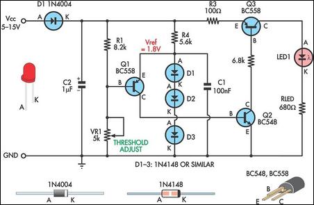
Low Supply Rail Detection
This is a simple low supply rail detection circuit that is inexpensive and can be assembled in approximately 20 minutes. It operates with low power consumption, making it suitable for integration into battery-powered devices. The circuit utilizes three low-cost transistors...
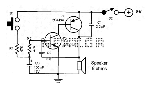
Noise making circuits
The core of the circuit is a two-transistor flasher with frequency modulation applied to the base of the first transistor. When the pushbutton is pressed, the oscillation frequency increases to a peak, and upon release, the frequency decreases due to...
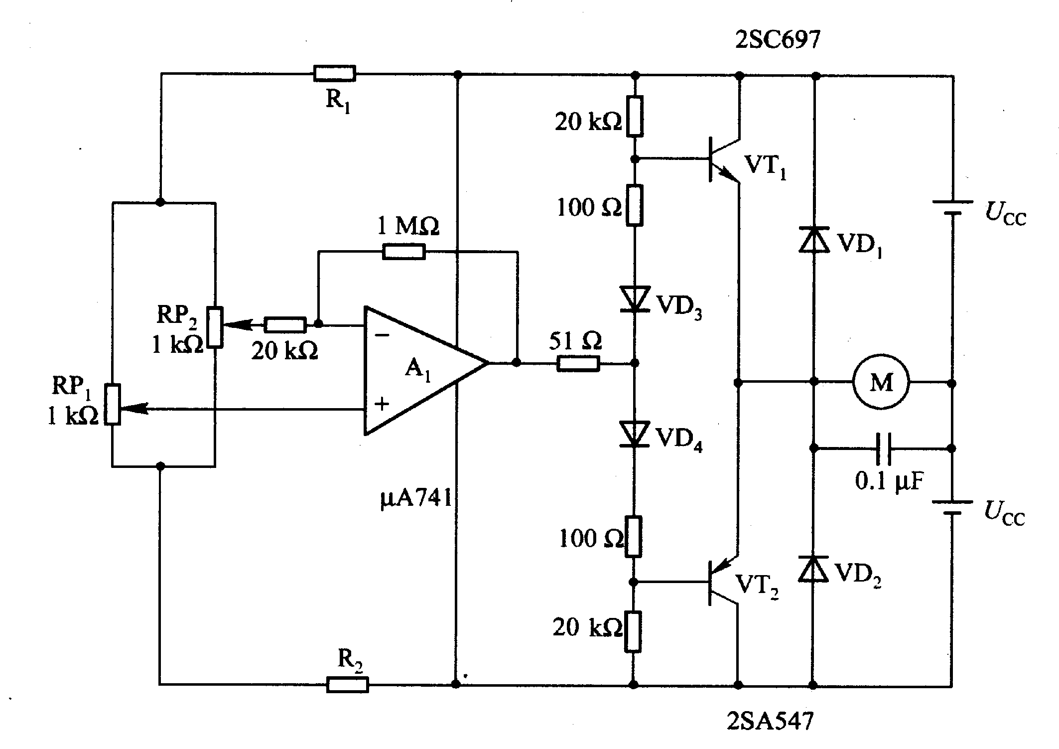
Motor time division control circuit composed of transistor and NE555
Figure 2-32 (a) illustrates the time control diagram for a motor operated by switch S1. When S1 is set to position 1, the power driver circuit supplies current to the motor, enabling it to run. When S1 is switched to...
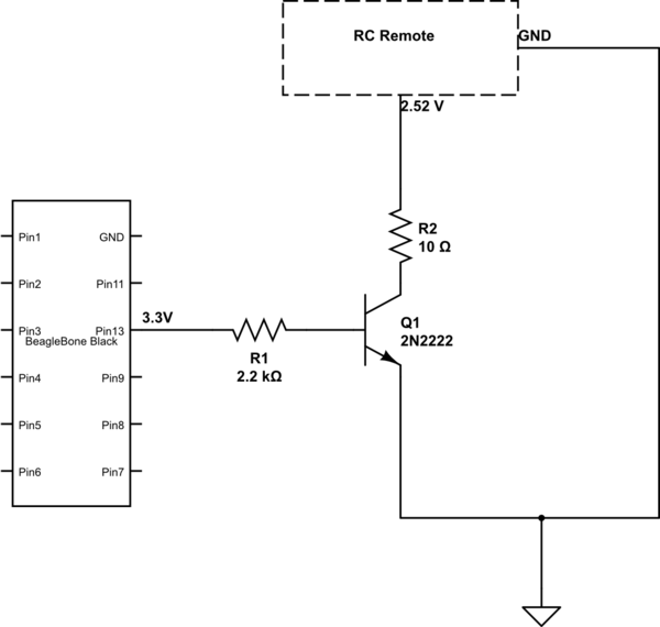
microcontroller Why this transistor logic as switch is not working
The remote control of an RC car was modified by extending wires from the backward, forward, left, and right switches. Grounding any of these wires completes the circuit and sends a signal to the car. The intention is to close...
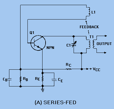
TUNED-COLLECTOR ARMSTRONG OSCILLATOR
The DC path is established from the negative side (ground) of VCC through RE, Q1, T1, and returns to the positive side of VCC. The figure clearly illustrates that both the AC and DC components flow through the tank circuit....
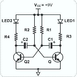
Astable Multivibrator with 2 Transistors
This circuit is straightforward and easy to construct, utilizing two transistors as active components along with several passive components such as resistors, capacitors, and two LEDs. The circuit employs the MPS2222 transistor, though any NPN type transistor can be used...
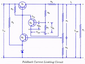
Controlled Transistor Series Regulator With Overload and Short-Circuit Protection
If the load resistance (RL) is reduced or the load terminals are accidentally shorted, a very large load current will flow, potentially damaging the pass transistor (Q1), diode, or other components. Fuse protection may not be sufficient, as the transistor...
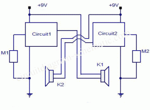
Simple Intercom Circuit Transistor
The circuit diagram represents a simple yet effective intercom system entirely based on transistors. It consists of three stages along with an RC amplifier. When the pushbutton S2 is pressed, the amplifier circuit around transistor T1 is activated.
The intercom circuit...