


Common collector amplifier via a DC and AC
#common collector
#transistor
#DC analysis
#AC analysis
#amplifier circuit
#signal amplification
#electronics
#bipolar junction transistor
#small signal
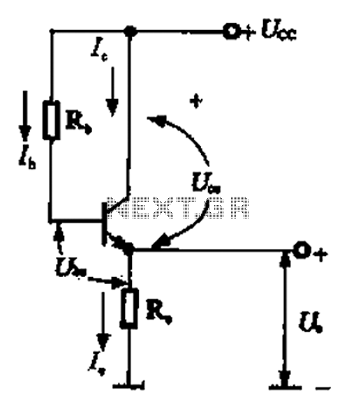
Description: A common collector amplifier can be analyzed through its DC and AC paths, as illustrated in Figure 1-14. The DC path is responsible for providing a biasing circuit for the power transistor, determining whether the transistor is in an active or cutoff state based on the biasing conditions. This circuit also supplies energy to the transistor. The AC path facilitates the functioning of the circuit, where an AC signal is treated as a short circuit, and the internal resistance of the power supply is influenced by the AC signal being shorted.
The common collector amplifier, also known as an emitter follower, is characterized by its ability to provide high input impedance and low output impedance. This configuration is particularly useful in applications where signal buffering is required. The DC analysis of the circuit involves determining the quiescent operating point, which is essential for ensuring that the transistor operates within its active region. The biasing network typically consists of resistors that set the base voltage, allowing for proper transistor operation.
In the AC analysis, the coupling capacitors are crucial as they block DC components while allowing AC signals to pass through. This ensures that the amplifier can respond to varying signal levels without affecting the DC bias point. The output signal, taken from the emitter, is a faithful reproduction of the input signal but with a lower voltage level, making it suitable for driving low-impedance loads.
The performance of the common collector amplifier can be further enhanced by considering factors such as temperature stability, frequency response, and power supply variations. Proper selection of components, including the transistor type and biasing resistors, is essential for optimizing the amplifier's characteristics for specific applications. Overall, the common collector amplifier serves as an effective solution for signal amplification and impedance matching in various electronic circuits. Common collector amplifier via a DC and AC (3) common-collector amplifier circuit DC and AC path when common collector amplifier circuit for analysis, can be divided into DC an d AC two paths shown in Figure 1-14. The DC path to provide a DC bias circuit of the circuit from the power transistor, the transistor is in an enlarged state or the off state, it is mainly determined by the bias. This circuit also provides energy for the transistor circuit. AC AC signal path is functioning circuit, a capacitor AC signal can be regarded as a short circuit, the internal resistance of the power supply also depends on the AC signal is short-circuited.
The common collector amplifier, also known as an emitter follower, is characterized by its ability to provide high input impedance and low output impedance. This configuration is particularly useful in applications where signal buffering is required. The DC analysis of the circuit involves determining the quiescent operating point, which is essential for ensuring that the transistor operates within its active region. The biasing network typically consists of resistors that set the base voltage, allowing for proper transistor operation.
In the AC analysis, the coupling capacitors are crucial as they block DC components while allowing AC signals to pass through. This ensures that the amplifier can respond to varying signal levels without affecting the DC bias point. The output signal, taken from the emitter, is a faithful reproduction of the input signal but with a lower voltage level, making it suitable for driving low-impedance loads.
The performance of the common collector amplifier can be further enhanced by considering factors such as temperature stability, frequency response, and power supply variations. Proper selection of components, including the transistor type and biasing resistors, is essential for optimizing the amplifier's characteristics for specific applications. Overall, the common collector amplifier serves as an effective solution for signal amplification and impedance matching in various electronic circuits. Common collector amplifier via a DC and AC (3) common-collector amplifier circuit DC and AC path when common collector amplifier circuit for analysis, can be divided into DC an d AC two paths shown in Figure 1-14. The DC path to provide a DC bias circuit of the circuit from the power transistor, the transistor is in an enlarged state or the off state, it is mainly determined by the bias. This circuit also provides energy for the transistor circuit. AC AC signal path is functioning circuit, a capacitor AC signal can be regarded as a short circuit, the internal resistance of the power supply also depends on the AC signal is short-circuited.
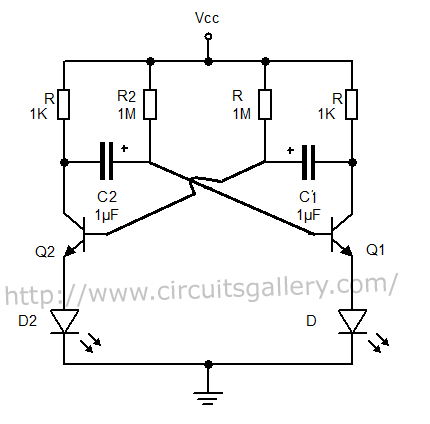
Astable Multivibrator using transistors
The output can also be taken from the collector terminals of the transistors, as illustrated in the circuit below. To understand the operation of the circuit, it is recommended to read about how a transistor functions as a switch.
In a...
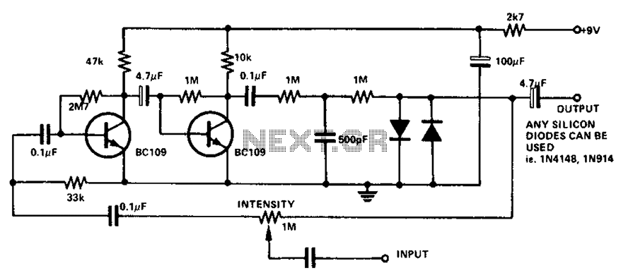
Boombox circuit diagram
The circuit utilizes a transistor to amplify the input signal. Two diodes are employed to clamp the distorted output, while a 500 pF capacitor filters out high-frequency noise. Under normal conditions, a 1M slide rheostat is used to adjust the...
2 transistor fm voice transmitter
This circuit functions as a voice transmitter utilizing a pair of BC548 transistors. While these transistors are not specifically designed for RF applications, they still yield satisfactory performance. An ECM microphone insert from Maplin Electronics, order code FS43W, is employed....
kode kunci satu transistor
This is the simplest electronic code lock circuit that can be constructed. The circuit utilizes one transistor, a relay, and a few passive components. Its simplicity does not compromise performance, as the circuit operates effectively. Essentially, it functions as a...
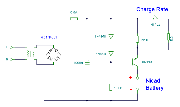
Nicad Battery Charger
This simple charger utilizes a single transistor as a constant current source. The voltage across a pair of 1N4148 diodes biases the base of the BD140 medium power transistor. The base-emitter voltage of the transistor and the forward voltage drop...
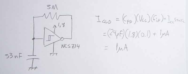
transistors Low power low voltage slow (0.1Hz) oscillator
The power supply varies, and the circuit must operate at under 10 µA of current (excluding the capacitor charging). It triggers a Silicon Controlled Rectifier (SCR) every 10 to 30 seconds as long as the power supply is above 1.8...
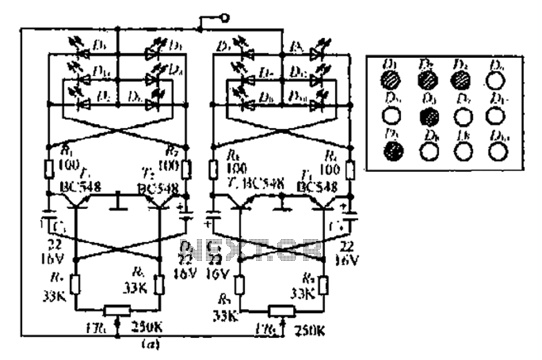
An adjustable bounce lighting circuit
A circuit involving oscillations is composed of a Houle Wang oscillator that utilizes a transistor configuration with components labeled Ti, n, and n, along with a composition of Q constants for the cycle. The waveform can be modified by changing...
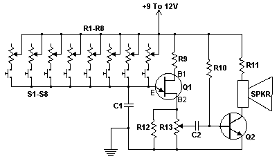
Transistor Organ
This simple circuit can provide hours of enjoyment as you learn tunes, play duets or just make some really weird sounds by pushing all the buttons at once. You have probably seen this circuit before, it is fairly common. I...
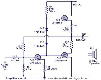
simple audio amplifier
The initial section of the circuit is a preamplifier that utilizes transistor Q1 (2N2222). The collector of transistor Q3 is connected to the base of transistor Q2 (2N2905A), which creates a complementary symmetry pair with Q3 (2N3053). The amplified signal...