


Effective output 50W distortion rate of 0.003% thick film hybrid amplifier
#hybrid amplifier
#low distortion
#50W output
#thick film
#capacitors
#audio amplifier
#power amplifier
#circuit design

Description: The main component of the circuit has been achieved using an integrated circuit (IC) with a significant number of bulk components, primarily capacitors. The internal circuit is designed to output from the differential amplifier using a PNP unipolar configuration, achieving a high gain. The amplitude of the mid-frequency class is substantial, and the conversion speed is determined by this stage. It is important to operate in high current conditions, utilizing a grounded base configuration to address high-frequency characteristics that may be adversely affected by the Miller effect. A transistor (Tr) is configured to establish a constant bias circuit, which helps to minimize power fluctuations caused by transient impacts. Another transistor (Tr) is employed to set the output bias, which also assists in temperature compensation by maintaining a stable voltage across the output. For large output currents, a Darlington connection is implemented at the output stage to enhance current gain.
The circuit design incorporates a differential amplifier at its core, utilizing a PNP transistor configuration to facilitate high gain performance. The use of numerous capacitors within the circuit serves to stabilize voltage levels and filter out noise, ensuring smooth operation across various frequencies. The output from the differential amplifier is critical, as it drives subsequent stages of the circuit.
In this configuration, the grounded base transistor arrangement plays a vital role in enhancing high-frequency response. By mitigating the Miller effect, which can degrade performance at elevated frequencies, the circuit maintains its fidelity and responsiveness. The constant biasing circuit is essential for stabilizing the operating point of the transistors, preventing fluctuations that could lead to distortion or inefficiency.
The inclusion of temperature compensation mechanisms is also noteworthy. The output bias transistor is designed to adjust for thermal variations, ensuring consistent performance even as environmental conditions change. This is particularly important in applications where the circuit may experience significant temperature fluctuations.
The output stage employs a Darlington pair configuration, which significantly increases current gain. This arrangement allows the circuit to drive larger loads without compromising performance, making it suitable for applications requiring high output currents. The combination of these design elements results in a robust circuit capable of delivering high performance while maintaining stability and reliability. As the main part of the circuit has been achieved Ic! Of bulk components are primarily large number of capacitors. Internal circuit shown, the output level from the A t, Tr. Co mposition current mirror circuit that converts the output of the differential amplifier PNP unipolar, and obtain a high gain of gain. The amplitude of the middle class is large, and the conversion speed is decided by this stage, we should try to make it work in high current, well make T ,.
Grounded base (and Tr, composition tllt to a shade amplifier), to solve the high-frequency characteristics caused by the deterioration of the Miller effect. rr. Change, Tr Po set for the constant bias circuit that can suppress the power generated by the impact. Tr, is used to set the output bias transistor, in addition to the base aims to take along a plate shot dead zone VBl voltage between the poles i also play a role in temperature compensation.
For large output current, the output stage Darlington connection, in order to improve electric foot magnification.
The circuit design incorporates a differential amplifier at its core, utilizing a PNP transistor configuration to facilitate high gain performance. The use of numerous capacitors within the circuit serves to stabilize voltage levels and filter out noise, ensuring smooth operation across various frequencies. The output from the differential amplifier is critical, as it drives subsequent stages of the circuit.
In this configuration, the grounded base transistor arrangement plays a vital role in enhancing high-frequency response. By mitigating the Miller effect, which can degrade performance at elevated frequencies, the circuit maintains its fidelity and responsiveness. The constant biasing circuit is essential for stabilizing the operating point of the transistors, preventing fluctuations that could lead to distortion or inefficiency.
The inclusion of temperature compensation mechanisms is also noteworthy. The output bias transistor is designed to adjust for thermal variations, ensuring consistent performance even as environmental conditions change. This is particularly important in applications where the circuit may experience significant temperature fluctuations.
The output stage employs a Darlington pair configuration, which significantly increases current gain. This arrangement allows the circuit to drive larger loads without compromising performance, making it suitable for applications requiring high output currents. The combination of these design elements results in a robust circuit capable of delivering high performance while maintaining stability and reliability. As the main part of the circuit has been achieved Ic! Of bulk components are primarily large number of capacitors. Internal circuit shown, the output level from the A t, Tr. Co mposition current mirror circuit that converts the output of the differential amplifier PNP unipolar, and obtain a high gain of gain. The amplitude of the middle class is large, and the conversion speed is decided by this stage, we should try to make it work in high current, well make T ,.
Grounded base (and Tr, composition tllt to a shade amplifier), to solve the high-frequency characteristics caused by the deterioration of the Miller effect. rr. Change, Tr Po set for the constant bias circuit that can suppress the power generated by the impact. Tr, is used to set the output bias transistor, in addition to the base aims to take along a plate shot dead zone VBl voltage between the poles i also play a role in temperature compensation.
For large output current, the output stage Darlington connection, in order to improve electric foot magnification.
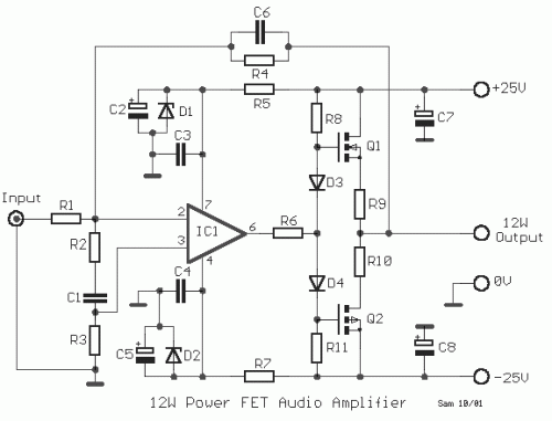
12W Audio Power Amplifier
12W Audio Power Amplifier Circuit Diagram. Features: small power amplifier, excellent sound quality, incorporates a fully integrated design.
The 12W audio power amplifier circuit is designed to provide high-quality audio amplification in a compact form factor. This amplifier is capable of...
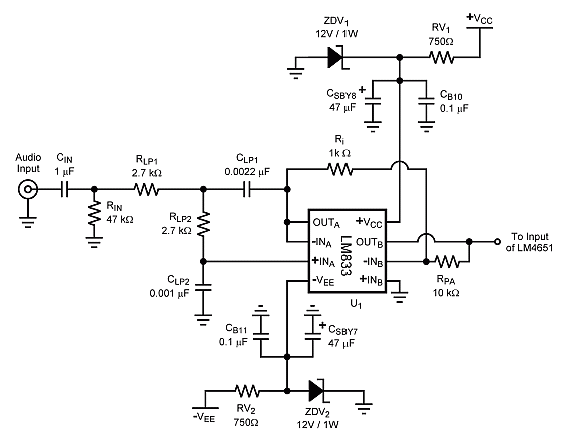
amplifier electronic circuits audio amp schematics 170w lm4651 lm4652
The ICs LM4651 and LM4652 are types of MOSFET integrated circuits and power amplifiers that include high-efficiency amplifiers, making them suitable for self-powered speakers, subwoofers, and high-quality car audio systems. The LM4651 is a fully integrated conventional pulse width modulation...
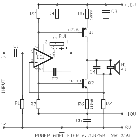
Power amplifier for Loudspeaker 6.5W 8R circuit
The amplifier circuit utilizes negative current feedback, which ensures that the load current is primarily influenced by the input signal rather than the loudspeaker's impedance. The inductor current from the loudspeaker generates a voltage across resistor R7, which is fed...
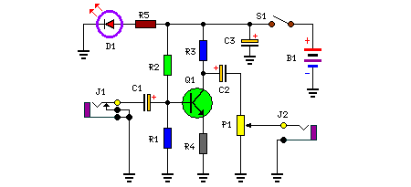
Audio Booster
This is a compact and portable unit that can be constructed on a veroboard. The amplifier's gain is nominally set at 20 dB, and its frequency response is primarily dictated by the component values used.
The design of the amplifier circuit...
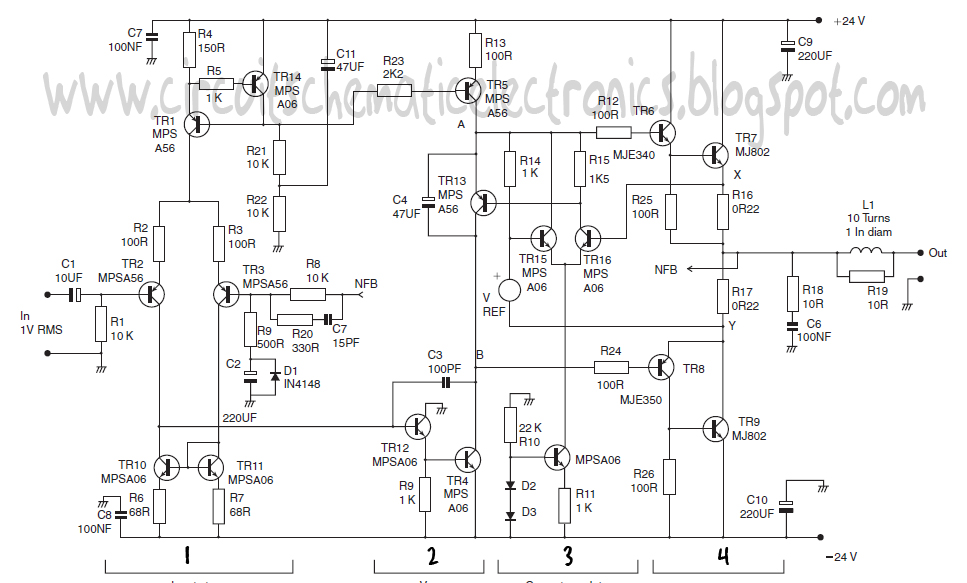
power amplifier class circuit
This design schematic represents a Class A power amplifier. It closely matches the operating parameters of Class B to facilitate comparison, particularly with a negative feedback (NFB) factor of 30dB at 20 kHz. The front end is similar to that...
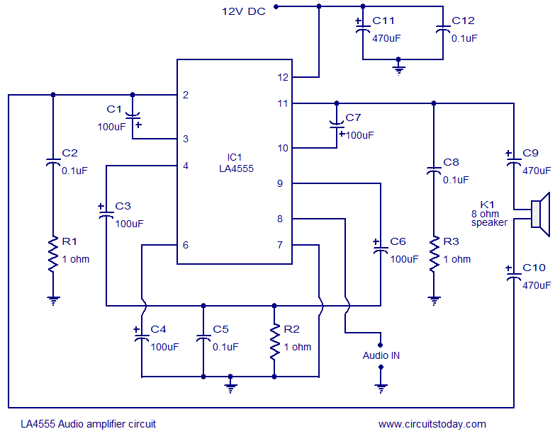
LA4550 audio amplifier circuit 4W 8 ohm 12V operation
The LA4550 audio amplifier operates in a BTL (Bridge-Tied Load) configuration. This amplifier is capable of delivering 4W into an 8-ohm load when powered by a 12V power supply.
The LA4550 is designed for audio amplification applications, particularly in situations where...
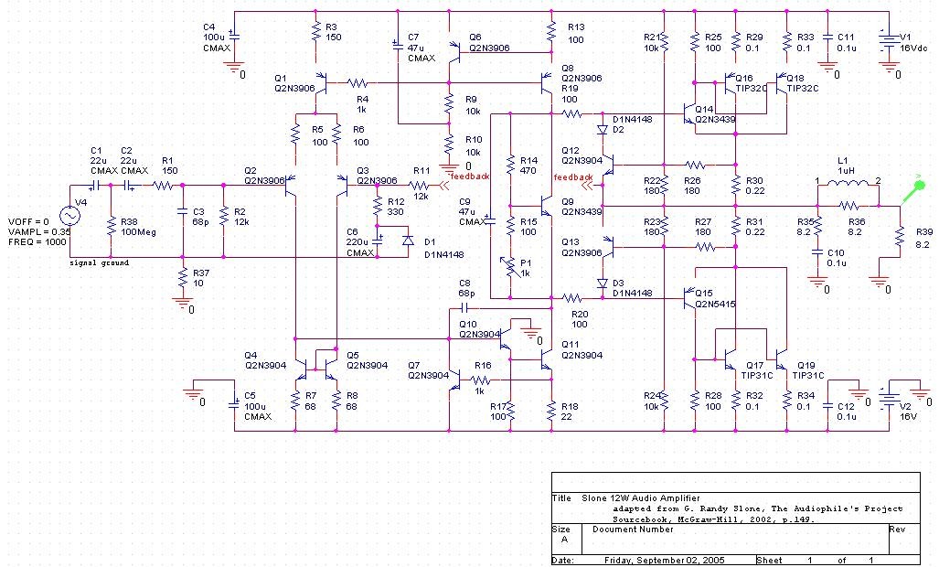
ECE 3434 Electronic Circuits II
The project involves developing a 12W power amplifier circuit into a fully assembled hard-wired unit. This will require a design cycle and development sequence that includes analysis, simulation, printed circuit board (PCB) layout, board population, hard soldering, and testing. If...
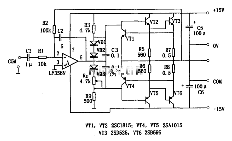
7W Audio Power Amplifier LF356
The circuit depicted is a low-frequency output 7W power amplifier. It employs a FET input operational amplifier, the LF356, for voltage amplification. The design features a transistor amplifier circuit that includes a driver stage. A significant negative feedback loop is...
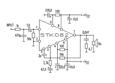
35w audio amplifier circuit by stk082
This amplifier circuit is suitable for home power audio devices. The STK082 amplifier specifications suggest that it can operate with supply voltages of up to ±43V. However, it is advisable to use no more than ±25V for 8-ohm loads, although...