


Eliminate loops cold junction compensation amplification circuit ISO102 INA101
#ISO102
#INA101
#thermocouple
#cold junction compensation
#ground loop elimination
#K-type thermocouple
#signal amplification
#high-end offset
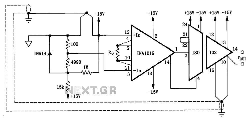
Description: The circuit, as illustrated in the figure, consists of an ISO102 and an INA101 designed to eliminate ground loops and provide high-end cold junction compensation for a thermocouple amplifier. This configuration utilizes a K-type thermocouple to detect temperature at the site, converting the temperature signal into a voltage signal that is subsequently amplified by the instrumentation amplifier INA101 before being processed by the ISO102 isolation amplifier. The resistance Rc is used to set the gain of the INA101. A notable feature of this circuit is that the K-type thermocouple is connected to the secondary ground of the ISO102, which helps maintain the same potential and thereby eliminates ground loops. Additionally, a 1N914 diode is employed for cold-junction compensation, while high-value resistors are used in the circuit.
The described circuit employs an ISO102 isolation amplifier in conjunction with an INA101 instrumentation amplifier to effectively manage the challenges associated with thermocouple signal processing, particularly in environments where ground loops may introduce noise and inaccuracies. The K-type thermocouple, known for its wide temperature range and reliability, serves as the primary sensor, detecting temperature variations in the environment.
The INA101 plays a crucial role in amplifying the low-level voltage signal generated by the thermocouple. The gain of the INA101 is adjustable through the resistor Rc, allowing for flexibility in signal amplification based on specific application requirements. This capability is essential for optimizing the circuit's performance, especially in applications where precise temperature measurements are critical.
Following the amplification stage, the ISO102 isolation amplifier provides electrical isolation, which is vital for protecting sensitive components from potential voltage spikes and ground loop interference. The design ensures that the secondary ground of the ISO102 is at the same potential as the K-type thermocouple, effectively mitigating ground loop issues that could otherwise distort the temperature readings.
The inclusion of a 1N914 diode for cold-junction compensation is a standard practice in thermocouple applications. This diode helps to adjust the output signal to account for variations in the reference junction temperature, thereby enhancing the accuracy of the temperature measurement. The use of high-value resistors in the circuit further aids in maintaining stability and minimizing thermal drift, ensuring reliable performance over time.
Overall, this circuit configuration exemplifies a robust solution for accurate temperature measurement using K-type thermocouples, particularly in industrial settings where ground loops and environmental noise may otherwise compromise data integrity. As shown in FIG constituted by ISO102 and INA101 have to eliminate ground loops, and high-end off cold junction compensation thermocouple amplifier. This circuit uses the K-typ e thermocouple temperature detected at the scene, the temperature signal is converted to a voltage signal after amplification instrumentation amplifier INA101 to ISO102, ISO102 after the isolation amplifier output. Wherein the resistance Rc for setting INA101 gain. The characteristics of this circuit is interfering K-type thermocouple and ISO102 secondary ground is connected, that the formation of the same potential, thereby eliminating ground loops caused.
Using 1N914 diode as thermocouple cold-junction compensation, lM resistors high off circuit.
The described circuit employs an ISO102 isolation amplifier in conjunction with an INA101 instrumentation amplifier to effectively manage the challenges associated with thermocouple signal processing, particularly in environments where ground loops may introduce noise and inaccuracies. The K-type thermocouple, known for its wide temperature range and reliability, serves as the primary sensor, detecting temperature variations in the environment.
The INA101 plays a crucial role in amplifying the low-level voltage signal generated by the thermocouple. The gain of the INA101 is adjustable through the resistor Rc, allowing for flexibility in signal amplification based on specific application requirements. This capability is essential for optimizing the circuit's performance, especially in applications where precise temperature measurements are critical.
Following the amplification stage, the ISO102 isolation amplifier provides electrical isolation, which is vital for protecting sensitive components from potential voltage spikes and ground loop interference. The design ensures that the secondary ground of the ISO102 is at the same potential as the K-type thermocouple, effectively mitigating ground loop issues that could otherwise distort the temperature readings.
The inclusion of a 1N914 diode for cold-junction compensation is a standard practice in thermocouple applications. This diode helps to adjust the output signal to account for variations in the reference junction temperature, thereby enhancing the accuracy of the temperature measurement. The use of high-value resistors in the circuit further aids in maintaining stability and minimizing thermal drift, ensuring reliable performance over time.
Overall, this circuit configuration exemplifies a robust solution for accurate temperature measurement using K-type thermocouples, particularly in industrial settings where ground loops and environmental noise may otherwise compromise data integrity. As shown in FIG constituted by ISO102 and INA101 have to eliminate ground loops, and high-end off cold junction compensation thermocouple amplifier. This circuit uses the K-typ e thermocouple temperature detected at the scene, the temperature signal is converted to a voltage signal after amplification instrumentation amplifier INA101 to ISO102, ISO102 after the isolation amplifier output. Wherein the resistance Rc for setting INA101 gain. The characteristics of this circuit is interfering K-type thermocouple and ISO102 secondary ground is connected, that the formation of the same potential, thereby eliminating ground loops caused.
Using 1N914 diode as thermocouple cold-junction compensation, lM resistors high off circuit.
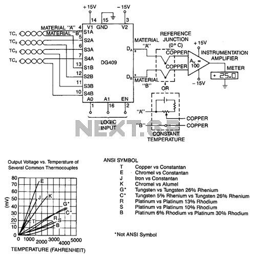
Thermocouple-multiplex-system
To decouple the sensors from the meter amplifier, either a reference junction at 0°C or a bucking voltage set at room temperature may be used. The latter method is simpler but is sensitive to changes in ambient temperature. The table...
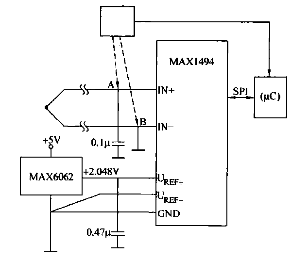
Thermocouple thermometer circuit
The circuit consists of the MAX1494 and a thermocouple temperature measurement system. The MAX1494 is terminated at 1N GND 5-32. An external temperature sensor, such as the DS75, can be utilized for junction temperature compensation. The MAX1494 employs an external...
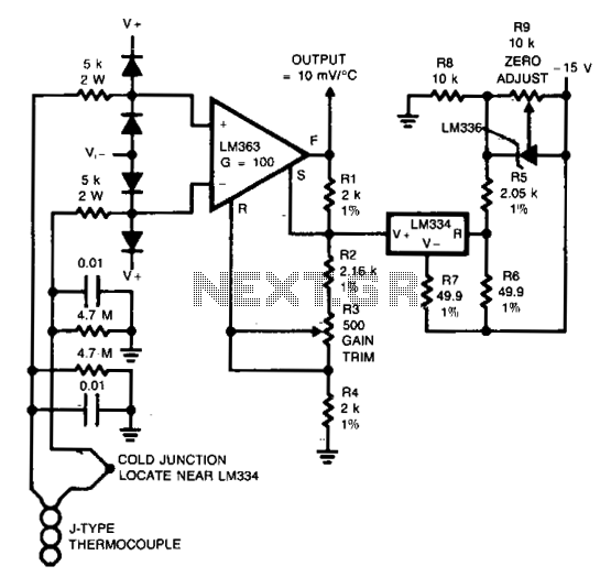
Thermocouple amplifier
Input protection circuitry allows the thermocouple to short to 120 Vac without damaging the amplifier. Calibration: Apply a 50 mV signal in place of the thermocouple. Trim R3 for V0UT = 12.25 V. Reconnect the thermocouple. More: Trim R9 for...
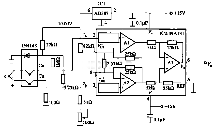
Thermocouple cold junction compensation amplifier circuit
The AD587 is a precision voltage reference providing a 10 V output, generated using a 27 kΩ resistor along with a compensation diode (1N4148) and a thermocouple. This setup connects to the VI + N terminal of a differential amplifier,...
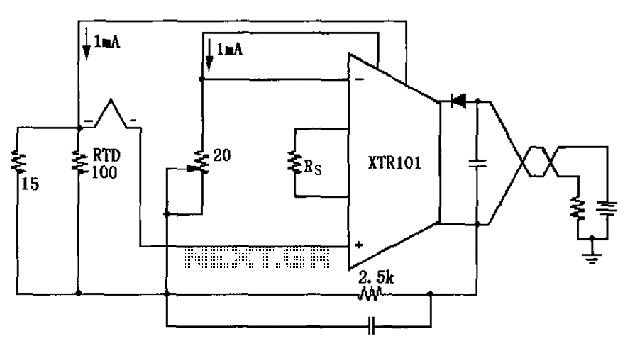
Thermocouple cold junction compensation RTD has XTR101 Input Circuit
The circuit utilizes a type J RTD (Resistance Temperature Detector), where the resistance value is directly related to the temperature. Calibration of the zero point is facilitated by a 20-ohm adjustment potentiometer as specified by the manufacturer.
The schematic features a...

Digital thermocouple thermometer
This digital thermocouple thermometer utilizes one active component and 15 passive components. The circuit is compatible with both type J and type K thermocouples. The type J thermocouple measures temperatures ranging from 10 to 530 °C with an accuracy of...
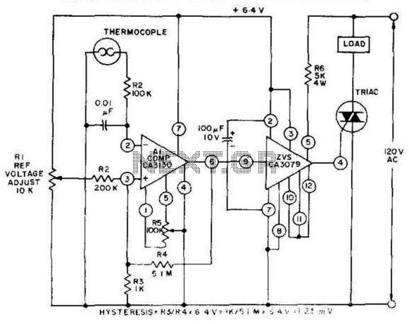
Thermocouple Temperature Control
This control, featuring zero-voltage load switching, utilizes a CA3130 BiMOS operational amplifier and a CA3079 zero-voltage switch. The CA3130, functioning as a comparator, is particularly suited for comparing the low voltages produced by a thermocouple against an adjustable reference voltage...
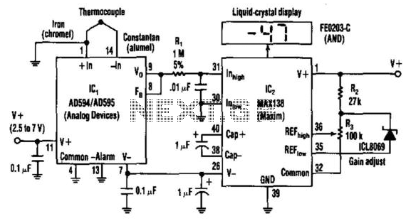
Single-Dc Supply Thermometer
Using a J-type thermocouple, this circuit can indicate temperatures from -350° to 400° with a 6-V supply or from -50° to +100° with a 3-V lithium battery. The AD954 produces a 10 mV/°C output to the MAX 138 digital voltmeter...
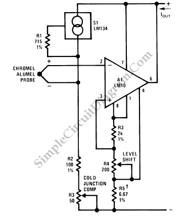
LM10 Thermocouple Current Loop Transmitter
A current loop transmitter refers to a sensor system utilized in industrial 4-20mA current loop technology. This transmitter contains the...
A current loop transmitter is a critical component in industrial automation and control systems, particularly in applications where analog signal transmission...