


Klipsch Promedia V.2-400 V4.1 V2.1 And V5.1 Amplifier Repair
#BASH amplifier
#circuit repair
#schematics
#audio amplifier
#ProMedia
#amplifier defects
#component tracing
#Evan Shultz
#circuit improvement
#audio repair
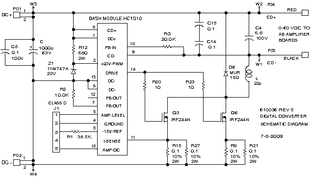
Description: The tracing of the BASH amplifier circuit for the V. 2-400 has been documented through schematics that reflect the findings. Design defects have been identified, and improvements are being implemented. Evan Shultz dedicated considerable time to tracing the circuits for the ProMedia V4.1 and V2.1, which involved removing components for value verification and replacing them. Following this, he proceeded to the ProMedia V5.1, acquiring one unit from Miguel Mejia and another from eBay. This effort has resulted in a complete representation of the ProMedia line from V2.1 to V5.1, providing customer support that Klipsch does not offer. The BASH amplifier circuit, while seemingly complex, operates with an AC power input of 117 volts, which is rectified to 156V DC on the Input-Output board. This voltage is then converted by a DC-to-DC converter to +/- 30 V DC, supplying power to LM340 and LM320 discrete IC regulators on the Input-Output board, which in turn power the audio IC preamplifier stages. The converter also provides a fixed 60 V DC to a component referred to as the Digital Converter, which is integral to the amplifier's operation. The voltage to the power amplifiers is maintained just above the output swing voltage through an audio processor that utilizes hybrid pulse-width modulation with a buck step-down converter. This converter operates by applying short pulses of high voltage to an inductor in series with the output load, allowing for the control of voltage across the load by adjusting the duration of these pulses. In this design, the two FETs that switch the high voltage are positioned in the return path, differing from typical configurations. The interconnections of the system show that the control pod and satellite speakers are separate units, while most connections are internal to the subwoofer. The DC-DC converter employs a 2-FET push-pull oscillator driving a transformer, with rectifiers on the transformer’s secondary producing the necessary voltages. Notable weaknesses in the design include under-rated components, particularly resistors that have shown signs of overheating and damage. Calculations indicate that some resistors are rated for only 50% of their maximum power, suggesting potential transient currents or high ambient temperatures within the subwoofer. For instance, resistor R27, designed as a 5-ohm component by paralleling two 10-ohm resistors, has been prone to failure due to under-rating.
The BASH amplifier circuit employs a sophisticated design that integrates various components to achieve efficient audio amplification. The AC power supply is first rectified to a high DC voltage, which is essential for the operation of the DC-DC converter. This converter plays a pivotal role in regulating the voltage levels required for the amplifier's operation. The use of LM340 and LM320 regulators ensures stable voltage outputs for the preamplifier stages, which are crucial for maintaining audio fidelity.
The Digital Converter, receiving a fixed 60 V DC, is responsible for managing the power amplifiers, ensuring that the voltage remains just above the output swing. This is accomplished through an innovative hybrid pulse-width modulation technique that adjusts the duty cycle of the voltage applied to the inductor, allowing for precise control over the output voltage levels. The buck step-down converter's unique configuration, with the FETs in the return path, enhances efficiency and reduces losses typically associated with conventional designs.
The design's weaknesses, particularly in the resistors, highlight the importance of component ratings in ensuring reliability and performance. The overheating issues observed suggest that the thermal management within the subwoofer enclosure may need to be addressed to prevent component failure. This could involve improving ventilation or selecting components with higher power ratings to accommodate potential transient conditions. The modifications made to resistor R27, replacing it with higher-rated components, exemplify the proactive measures taken to enhance the amplifier's durability and performance.
Overall, the BASH amplifier circuit represents a blend of innovative design and practical challenges, with ongoing efforts to refine and optimize its performance for enhanced audio output.I began tracing the BASH amplifier circuit for my V. 2-400. The following schematics are my best effort to document what I found. I have also described design defects I have found and what I am doing to improve them. Evan Shultz spent an amazing amount of time tracing the circuits for his ProMedia V4. 1 and V2. 1. This tracing included removing some components to check their value and replacing them. If you think this is not an amazing amout of work, you have never tried it. After generating schematics of the ProMedia V4. 1 and V2. 1, Evan moved on to the ProMedia V5. 1. Miguel Mejia provided a V5. 1, and Evan bought another V5. 1 off E-bay. So now we have the complete Promedia line from V2. 1 to V5. 1, giving you the customer support that Klipsch would never provide. The BASH amplifier is not as complicated as it first appears. AC power of 117 volts is rectified to 156Vdc on the Input-Output board, and then goes to to the DC-to-DC converter. The converter drops the 156Vdc to +/- 30 Vdc that goes to LM340 and LM320 discrete IC regulators on the Input-Output board.
From these regulators, the audio IC preamplifier stages get powered up. The converter also supplies a fixed 60-Vdc to what Indigo calls a Digital Converter. The Digital Converter is the heart of the BASH amplifier. Voltage to the power amplifiers is kept just a few volts above the amplifier`s output swing voltage by an audio processor hybrid pulse-width modulating a buck step-down converter. A buck step-down converter operates by applying short pulses of high voltage to an inductor in series with its output load.
These pulses flow through the inductor, which builds a magnetic field. The collapse of the magnetic field between pulses keeps the current flowing at a constant rate into its load and back to the inductor through a diode. The voltage across the buck converter`s load can be increased or decreased by changing the time the high voltage is applied to the inductor.
Unlike the typical buck stepdown converter, in this design, the two FETs in parrallel that switch the high voltage are in the return path. Below are the interconnections for the system. The control pod and the satellite speakers shown are separate units; all other connections are internal to the subwoofer box.
Okay, so now we look at the individual pieces of the amplifier. The DC-DC converter is a 2-FET, push-pull oscillator driving a transformer. From the secondary of the transformer rectifiers produce the 60 Vdc and +30/0/-30 Vdc. Weaknesses in the design are under-rated components. I have calculated the power dissipation of some of these resistors and they appear to be properly rated at 50% of maximum power. However, they have definitely been hot, to the point of scorching the resistor so badly that the color rings can`t be read.
I have to assume that there is some transient current not accounted for, or that the ambient temperature inside the subwoofer is very high when the system is not being used. This would exceed the power limits at the moment the speakers were first used, which agrees with some of the reports of failure right after begining to use the speakers.
Resistor R27 is 5 ohms and is made by putting two 10-ohm resistors in parallel, one on the top of the pc board, and one on the back of the board. These are under-rated and burn up. I changed these to two, 10-ohm, 5%, 1
The BASH amplifier circuit employs a sophisticated design that integrates various components to achieve efficient audio amplification. The AC power supply is first rectified to a high DC voltage, which is essential for the operation of the DC-DC converter. This converter plays a pivotal role in regulating the voltage levels required for the amplifier's operation. The use of LM340 and LM320 regulators ensures stable voltage outputs for the preamplifier stages, which are crucial for maintaining audio fidelity.
The Digital Converter, receiving a fixed 60 V DC, is responsible for managing the power amplifiers, ensuring that the voltage remains just above the output swing. This is accomplished through an innovative hybrid pulse-width modulation technique that adjusts the duty cycle of the voltage applied to the inductor, allowing for precise control over the output voltage levels. The buck step-down converter's unique configuration, with the FETs in the return path, enhances efficiency and reduces losses typically associated with conventional designs.
The design's weaknesses, particularly in the resistors, highlight the importance of component ratings in ensuring reliability and performance. The overheating issues observed suggest that the thermal management within the subwoofer enclosure may need to be addressed to prevent component failure. This could involve improving ventilation or selecting components with higher power ratings to accommodate potential transient conditions. The modifications made to resistor R27, replacing it with higher-rated components, exemplify the proactive measures taken to enhance the amplifier's durability and performance.
Overall, the BASH amplifier circuit represents a blend of innovative design and practical challenges, with ongoing efforts to refine and optimize its performance for enhanced audio output.I began tracing the BASH amplifier circuit for my V. 2-400. The following schematics are my best effort to document what I found. I have also described design defects I have found and what I am doing to improve them. Evan Shultz spent an amazing amount of time tracing the circuits for his ProMedia V4. 1 and V2. 1. This tracing included removing some components to check their value and replacing them. If you think this is not an amazing amout of work, you have never tried it. After generating schematics of the ProMedia V4. 1 and V2. 1, Evan moved on to the ProMedia V5. 1. Miguel Mejia provided a V5. 1, and Evan bought another V5. 1 off E-bay. So now we have the complete Promedia line from V2. 1 to V5. 1, giving you the customer support that Klipsch would never provide. The BASH amplifier is not as complicated as it first appears. AC power of 117 volts is rectified to 156Vdc on the Input-Output board, and then goes to to the DC-to-DC converter. The converter drops the 156Vdc to +/- 30 Vdc that goes to LM340 and LM320 discrete IC regulators on the Input-Output board.
From these regulators, the audio IC preamplifier stages get powered up. The converter also supplies a fixed 60-Vdc to what Indigo calls a Digital Converter. The Digital Converter is the heart of the BASH amplifier. Voltage to the power amplifiers is kept just a few volts above the amplifier`s output swing voltage by an audio processor hybrid pulse-width modulating a buck step-down converter. A buck step-down converter operates by applying short pulses of high voltage to an inductor in series with its output load.
These pulses flow through the inductor, which builds a magnetic field. The collapse of the magnetic field between pulses keeps the current flowing at a constant rate into its load and back to the inductor through a diode. The voltage across the buck converter`s load can be increased or decreased by changing the time the high voltage is applied to the inductor.
Unlike the typical buck stepdown converter, in this design, the two FETs in parrallel that switch the high voltage are in the return path. Below are the interconnections for the system. The control pod and the satellite speakers shown are separate units; all other connections are internal to the subwoofer box.
Okay, so now we look at the individual pieces of the amplifier. The DC-DC converter is a 2-FET, push-pull oscillator driving a transformer. From the secondary of the transformer rectifiers produce the 60 Vdc and +30/0/-30 Vdc. Weaknesses in the design are under-rated components. I have calculated the power dissipation of some of these resistors and they appear to be properly rated at 50% of maximum power. However, they have definitely been hot, to the point of scorching the resistor so badly that the color rings can`t be read.
I have to assume that there is some transient current not accounted for, or that the ambient temperature inside the subwoofer is very high when the system is not being used. This would exceed the power limits at the moment the speakers were first used, which agrees with some of the reports of failure right after begining to use the speakers.
Resistor R27 is 5 ohms and is made by putting two 10-ohm resistors in parallel, one on the top of the pc board, and one on the back of the board. These are under-rated and burn up. I changed these to two, 10-ohm, 5%, 1
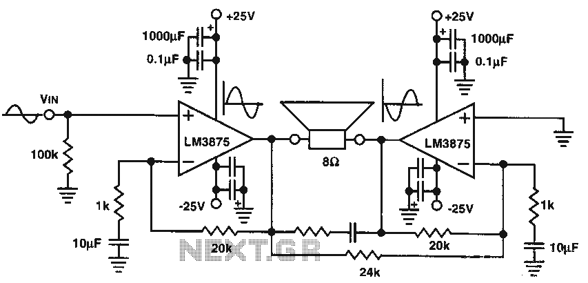
8W audio amplifier IC circuit
The audio power amplifier delivers 80W of audio power to an 8-ohm load. The LM3875 integrated circuit (IC) requires adequate cooling. It is important to note that in the bridge amplifier configuration, the two connected speakers will produce heat.
The audio...
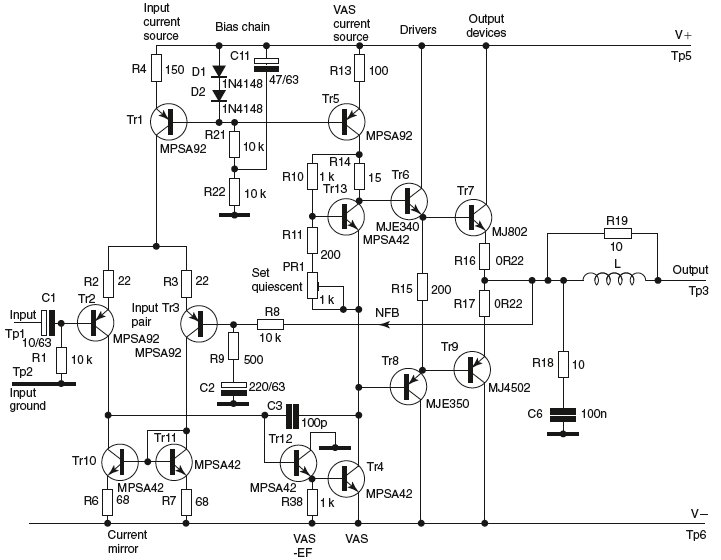
Audio amplifier power supply design
This document discusses the advantages and disadvantages of various power supply technologies, along with the design considerations necessary for selecting and evaluating a mains transformer. It covers the pros and cons of external supplies, inrush current control, RF emissions from...
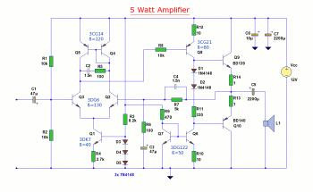
5W Audio Amplifier Circuit based BD139/BD140
The diagram illustrates a 5W audio amplifier circuit constructed using power transistors BD139 and BD140 for the final amplification stage. This compact amplifier serves as a general-purpose amplifier suitable for applications such as computer audio, radio, MP3 players, and video...
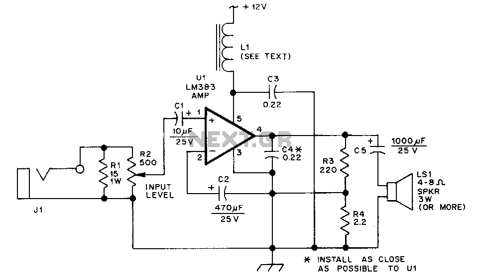
Speaker-amplifier
The LM383 is an audio power amplifier capable of delivering up to 8 watts of audio output. Resistor R1 serves as a load resistor for the audio output of a hand-held transceiver. Resistor R2 can be implemented using two fixed...
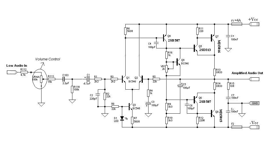
Hi-fi Audio Amplifier Circuit Design and implementation
Designing an audio amplifier from scratch using discrete components is an engaging task, as it enables users to create amplifiers that meet diverse requirements. Audio amplifiers can enhance low-level sounds from mobile devices, making them louder and more vibrant. Based...
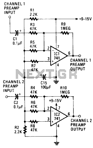
Walkman amplifier II
The gain of the low-cost integrated circuit (IC) is internally fixed at no less than 34 dB (50 times). A unique input stage allows input signals to be referenced to ground. The output is automatically self-centering to one-half the supply...
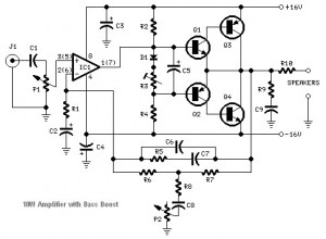
Transistored 10W Audio Amplifier
This audio amplifier circuit is based on the operational amplifier NE5532 and utilizes a pair of power transistors, TIP41A and TIP42A. It is capable of delivering up to 10W of audio power output into an 8-ohm speaker. The design is...
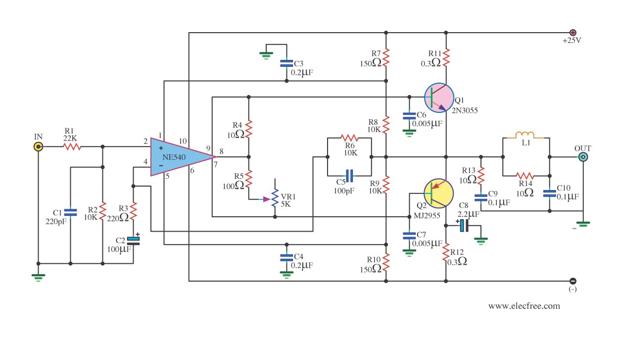
Small class b audio amplifier circuit diagram
When the power supply reaches the circuit and the input signal is applied, the sound signal is processed through capacitor C1 and resistor R1 for signal coupling and noise reduction. The modified signal then reaches pin 3 (non-inverting) of operational...
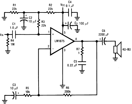
Circuit of power audio amplifier lm1875 20W
The LM1875 is a monolithic audio amplifier that provides very low distortion and high-quality performance for audio amplifier projects. The LM1875 delivers 20 watts into loads of 4 Ohms or 8 Ohms.
The LM1875 audio amplifier is designed for applications requiring...