


LM2876 amplifier configuration
#LM2876
#power amplifier
#emitter follower
#audio amplifier
#transistor
#single power supply
#neutral level
#external transistor
#circuit reliability
#amplifier configuration
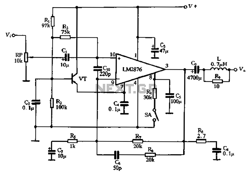
Description: A single power amplifier circuit using the LM2876 IC is designed. An external transistor (VTf) is configured to form an emitter follower, which provides a neutral level (7 feet) for the LM2876, ensuring reliable noise suppression in the circuit along with the associated bias circuitry. A mute switch (SA) is included, as well as a potentiometer (RP) for volume control. Capacitor C4, with a capacitance value of 7 feet, is connected to the AC ground, serving to enhance the common mode rejection ratio of the amplifier and ultimately improve sound quality.
The LM2876 power amplifier circuit is a robust design intended for audio applications, featuring an integrated circuit that simplifies the amplification process while ensuring high fidelity. The use of an external transistor configured as an emitter follower allows for a stable output level, which is essential for maintaining audio quality. This configuration also aids in minimizing distortion and enhancing the linearity of the amplifier's response.
The mute switch (SA) is strategically placed within the circuit to allow for quick disengagement of the amplifier output, providing a means to silence the audio without altering the gain settings. This feature is particularly beneficial in scenarios where immediate silence is required, such as during interruptions or transitions between audio sources.
The potentiometer (RP) serves as a variable resistor, allowing the user to adjust the volume of the audio output. This component is critical for user interaction, providing a simple yet effective means to control sound levels according to the listener's preference.
Capacitor C4 plays a significant role in the overall performance of the amplifier. By connecting it to the AC ground, it acts as a filter that improves the common mode rejection ratio (CMRR). A higher CMRR indicates better performance in rejecting noise that may affect the audio signal, leading to clearer sound reproduction. The choice of a 7-foot capacitance value is specifically aimed at optimizing the frequency response and enhancing the amplifier's ability to handle various audio signals without introducing unwanted artifacts.
In summary, this power amplifier circuit design effectively integrates various components to ensure high-quality audio output while providing user-friendly features such as volume control and a mute function. The careful selection of components and their configuration is crucial for achieving optimal performance in audio applications.A single power amplifier circuit LM2876 crrL constituted. VTf external transistor to form the emitter type to provide neutral level (7 feet) for the LM2876, guaranteed lC relia ble noise suppression circuit and associated circuitry bias. Mute switch button switch SA. Potentiometer RP for the volume control. Capacitor C4 is 7 foot AC ground capacitance, the purpose is to improve the common mode rejection ratio of the amplifier, power amplifier to improve sound quality.
The LM2876 power amplifier circuit is a robust design intended for audio applications, featuring an integrated circuit that simplifies the amplification process while ensuring high fidelity. The use of an external transistor configured as an emitter follower allows for a stable output level, which is essential for maintaining audio quality. This configuration also aids in minimizing distortion and enhancing the linearity of the amplifier's response.
The mute switch (SA) is strategically placed within the circuit to allow for quick disengagement of the amplifier output, providing a means to silence the audio without altering the gain settings. This feature is particularly beneficial in scenarios where immediate silence is required, such as during interruptions or transitions between audio sources.
The potentiometer (RP) serves as a variable resistor, allowing the user to adjust the volume of the audio output. This component is critical for user interaction, providing a simple yet effective means to control sound levels according to the listener's preference.
Capacitor C4 plays a significant role in the overall performance of the amplifier. By connecting it to the AC ground, it acts as a filter that improves the common mode rejection ratio (CMRR). A higher CMRR indicates better performance in rejecting noise that may affect the audio signal, leading to clearer sound reproduction. The choice of a 7-foot capacitance value is specifically aimed at optimizing the frequency response and enhancing the amplifier's ability to handle various audio signals without introducing unwanted artifacts.
In summary, this power amplifier circuit design effectively integrates various components to ensure high-quality audio output while providing user-friendly features such as volume control and a mute function. The careful selection of components and their configuration is crucial for achieving optimal performance in audio applications.A single power amplifier circuit LM2876 crrL constituted. VTf external transistor to form the emitter type to provide neutral level (7 feet) for the LM2876, guaranteed lC relia ble noise suppression circuit and associated circuitry bias. Mute switch button switch SA. Potentiometer RP for the volume control. Capacitor C4 is 7 foot AC ground capacitance, the purpose is to improve the common mode rejection ratio of the amplifier, power amplifier to improve sound quality.
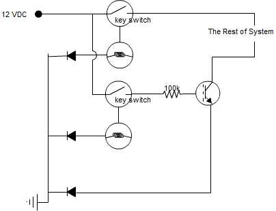
transistor as a switch circuit problems
A circuit is being designed that incorporates two key switches, which must both be closed for current to flow through the circuit.
The proposed circuit configuration employs two key switches connected in series. In this arrangement, the current can only pass...
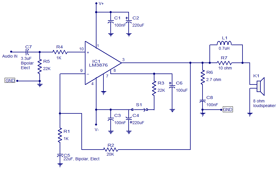
50 watt audio amplifier based on LM3876
LM3876-based 50-watt audio amplifier circuit. Operates from +/-35V DC. Simple design, low noise.
The LM3876 is a high-performance audio power amplifier designed for driving speakers in various audio applications. This particular circuit configuration enables the amplifier to deliver up to 50...
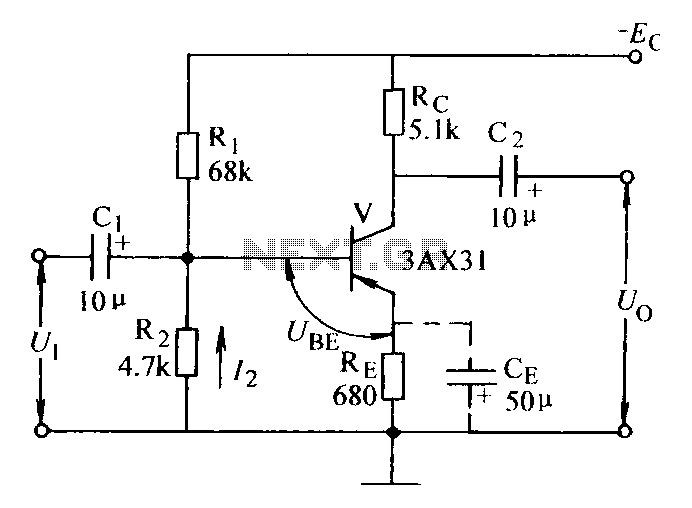
Current negative feedback voltage divider biasing circuit diagram
Current negative feedback voltage divider biased circuit diagram.
The current negative feedback voltage divider biased circuit is a configuration commonly used in electronic amplifiers to stabilize the operating point and improve linearity. This circuit typically consists of an amplifier, a voltage...
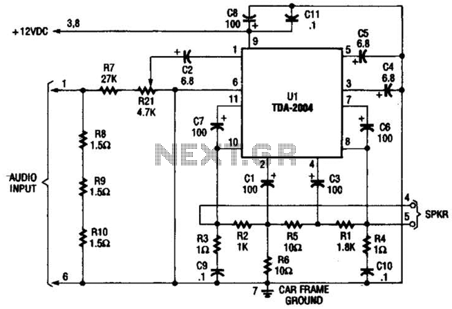
Booster Amplifier For Car Stereo Use Circuit
Only one channel of this circuit is shown. The other is practically identical. The input to the circuit, taken from the speaker output of a car radio, is divided into two paths. In one path, a high-power divider network (comprising...
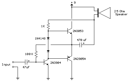
80mW Audio Amplifier
This circuit is similar to the one above but uses positive feedback to get a little more amplitude to the speaker. I copied it from a small 5 transistor radio that uses a 25 ohm speaker. In the circuit above,...
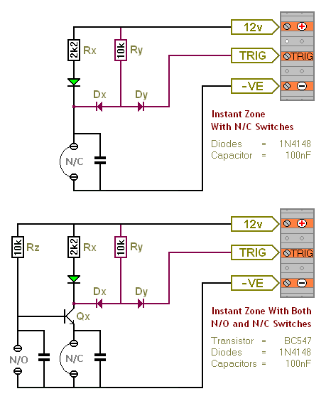
Transistor Based Burglar Alarm - Adding Extra Zones
The Transistor Burglar Alarm System allows for the addition of multiple extra zones. The primary circuit is compatible with standard normally-closed input devices, including magnetic reed contacts, micro switches, foil tape, and passive infrared sensors (PIRs). An auxiliary circuit provides...
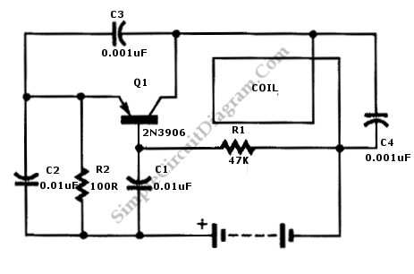
Single Transistor Metal Locator
This is a metal locator circuit designed to detect metal objects. The circuit utilizes an AM radio and a one-transistor oscillator.
The metal locator circuit operates by generating an oscillating signal that can be influenced by the presence of metal. The...
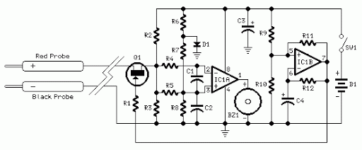
Quick On-Board Junction TesterCircuit
Acoustic check of transistor and diode junctions. Also suitable as a continuity tester. Short circuits or broken PCB tracks can be easily recognized.
The acoustic check of transistor and diode junctions is a method used to assess the functionality of these...
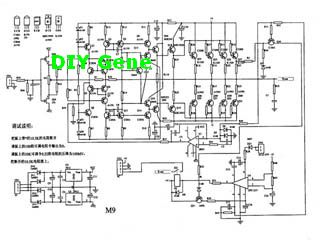
Complete Solid state M-9 Power Amplifier
The following circuit illustrates a complete solid-state M-9 power amplifier circuit diagram. Features include a DC servo that acts as a loudspeaker protection circuit.
The solid-state M-9 power amplifier circuit is designed to deliver high-quality audio amplification while ensuring the safety...