


LM386 voice audio power amplifier circuit design project
#LM386
#audio amplifier
#low voltage
#variable gain
#volume control
#power amplifier
#voice amplifier
#consumer applications
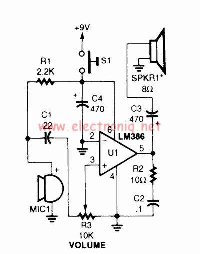
Description: A voice amplifier can be designed using the LM386 power amplifier, which is intended for low voltage consumer applications. This simple circuit features variable gain and volume control. The gain is set internally to 20 to minimize the number of external components; however, by adding an external resistor and capacitor between pins 1 and 8, the gain can be increased to any value ranging from 20 to 200.
The LM386 is a low voltage audio amplifier designed to operate from a single power supply, typically between 4V and 12V, making it suitable for battery-powered devices. The device is housed in an 8-pin DIP package, which simplifies integration into various circuit designs.
In this application, the voice amplifier circuit can be constructed with minimal components. The basic configuration includes the LM386 IC, a power supply, a variable resistor for volume control, and an external resistor-capacitor (RC) network connected between pins 1 and 8 to adjust the gain. The variable resistor can be implemented as a potentiometer, allowing for user-adjustable volume levels.
The gain setting can be modified by selecting appropriate resistor and capacitor values. For example, if a gain of 50 is desired, one could use a resistor of 1.2 kΩ and a capacitor of 10 µF, following the formula for gain calculation in the LM386. It is crucial to ensure that the selected components are rated for the operating voltage and frequency range of the application to maintain performance and reliability.
To enhance the performance of the amplifier further, bypass capacitors can be added near the power supply pins to filter out noise, ensuring clean audio output. Additionally, a coupling capacitor can be placed at the output to block any DC offset, allowing only the amplified AC audio signal to pass through.
Overall, the LM386-based voice amplifier circuit is efficient, cost-effective, and versatile, suitable for various low-power audio applications, including portable speakers, intercom systems, and hearing aids.Using LM386 power amplifier designed for use in low voltage consumer applications can be designed a very simple voice amplifier with variable gain and volume control. The gain is internally set to 20 to keep external part count low, but the addition of an external resistor and capacitor between pins 1 and 8 will increase the gain to any value from
20 to 200.
The LM386 is a low voltage audio amplifier designed to operate from a single power supply, typically between 4V and 12V, making it suitable for battery-powered devices. The device is housed in an 8-pin DIP package, which simplifies integration into various circuit designs.
In this application, the voice amplifier circuit can be constructed with minimal components. The basic configuration includes the LM386 IC, a power supply, a variable resistor for volume control, and an external resistor-capacitor (RC) network connected between pins 1 and 8 to adjust the gain. The variable resistor can be implemented as a potentiometer, allowing for user-adjustable volume levels.
The gain setting can be modified by selecting appropriate resistor and capacitor values. For example, if a gain of 50 is desired, one could use a resistor of 1.2 kΩ and a capacitor of 10 µF, following the formula for gain calculation in the LM386. It is crucial to ensure that the selected components are rated for the operating voltage and frequency range of the application to maintain performance and reliability.
To enhance the performance of the amplifier further, bypass capacitors can be added near the power supply pins to filter out noise, ensuring clean audio output. Additionally, a coupling capacitor can be placed at the output to block any DC offset, allowing only the amplified AC audio signal to pass through.
Overall, the LM386-based voice amplifier circuit is efficient, cost-effective, and versatile, suitable for various low-power audio applications, including portable speakers, intercom systems, and hearing aids.Using LM386 power amplifier designed for use in low voltage consumer applications can be designed a very simple voice amplifier with variable gain and volume control. The gain is internally set to 20 to keep external part count low, but the addition of an external resistor and capacitor between pins 1 and 8 will increase the gain to any value from
20 to 200.
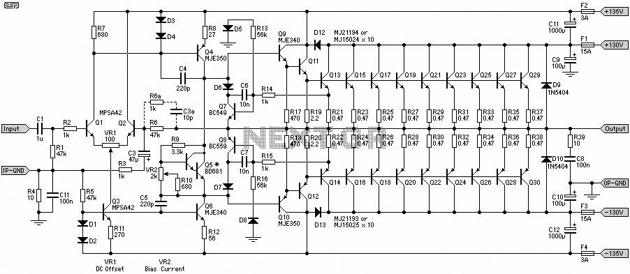
1500W Power Amplifier
A 1500W power amplifier circuit design diagram created by Rod Elliott. The circuit utilizes 10 pairs of power transistors, specifically MJ15024 and MJ15025, or alternatively MJ21193 and MJ21194.
The 1500W power amplifier circuit is designed for high-performance audio applications, providing significant...

250mW audio Amplifier
This design can be used as a small booster. The amplifier is built around a balance stage. The quiescent current is set by diodes D1 and D2. The simplicity of the circuit, the quiescent current depends on the temperature of...
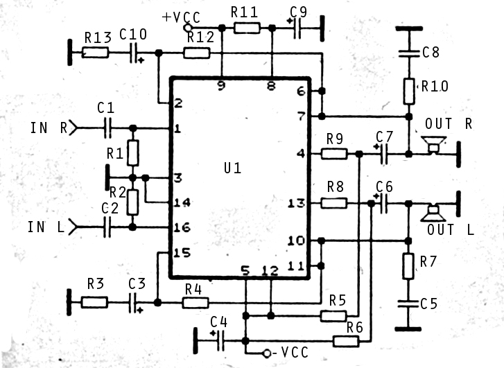
2x30watt home amplifier circuit
The audio amplifier circuit is highly suitable for home use, particularly with subwoofer or woofer speakers. Commonly referred to as a home amplifier, these audio amplifiers are based on integrated circuits (ICs), specifically the STK series, which includes models such...
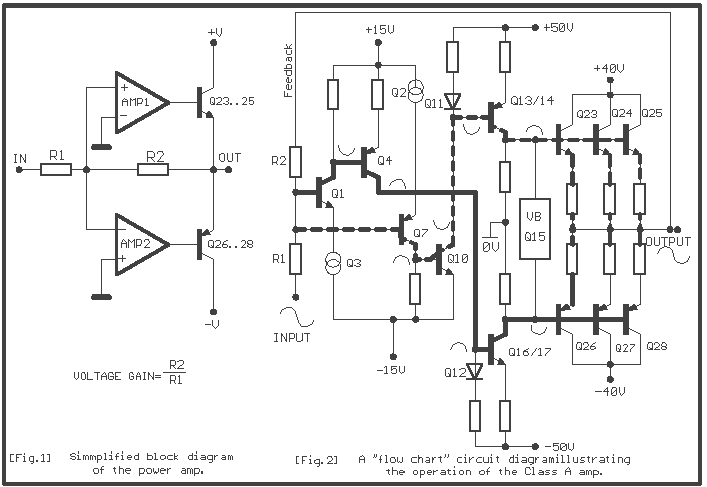
Power amplifier 60W Class A
The simplified circuit [Fig.2] shows that each sub-amplifier consists of two voltage gain stages. The first stage consists of a complementary two stage common emitter [Q1-7] whose gain is about x2.3. The second stage is a current mirror stage [Q13-14]...
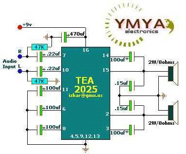
Stereo Audio Amplifier 2x2W or mono 5W ( TEA2025 )
These circuits are based on TEA2025, a monolithic integrated audio amplifier in a 16-pin plastic dual in-line package manufactured by UTC. The circuit includes an internal thermal protector and is designed for portable cassette players and radios. It can also...
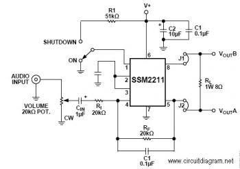
1.5W Audio Amplifier with IC SSM2211
The SSM22111 is a high-performance audio amplifier that delivers 1 W RMS of low distortion audio power into a bridge-connected 8-ohm speaker load (or 1.5 W RMS into a 4-ohm load). The SSM2211 operates over a wide temperature range and...
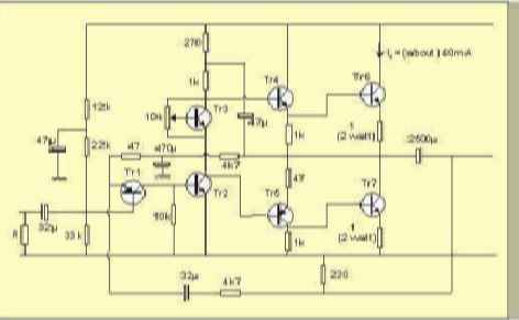
10w audio amplifier
The table below illustrates the expected voltages when utilizing a 24V supply, with the variable resistor adjusted to provide an output current of approximately 40mA.
The circuit operates with a 24V DC power supply, where a variable resistor (also known as...
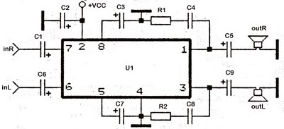
stereo tda2822 audio power amplifier
This series utilizes the TDA2822M integrated circuit (IC) as the primary amplifier. Additionally, alternative ICs such as KA2209, NJM2073, U2822B, and U2823B can be employed alongside the TDA2822M. The output power is limited to a maximum of 4 watts, indicating...
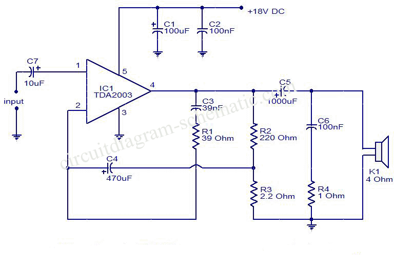
10 w amplifier using tda2003
This is a circuit diagram of an audio amplifier circuit featuring a 10W power amplifier using the TDA2003 integrated circuit from SGS Thomson. The IC is capable of delivering 10W into a 4-ohm load at a supply voltage of 18V...