


LM4910 minimum output noise reduce the output power circuit
#LM4910
#output noise reduction
#audio amplifier
#power reduction
#resistor
#output terminal
#circuit design
#noise measures
#load
#signal integrity
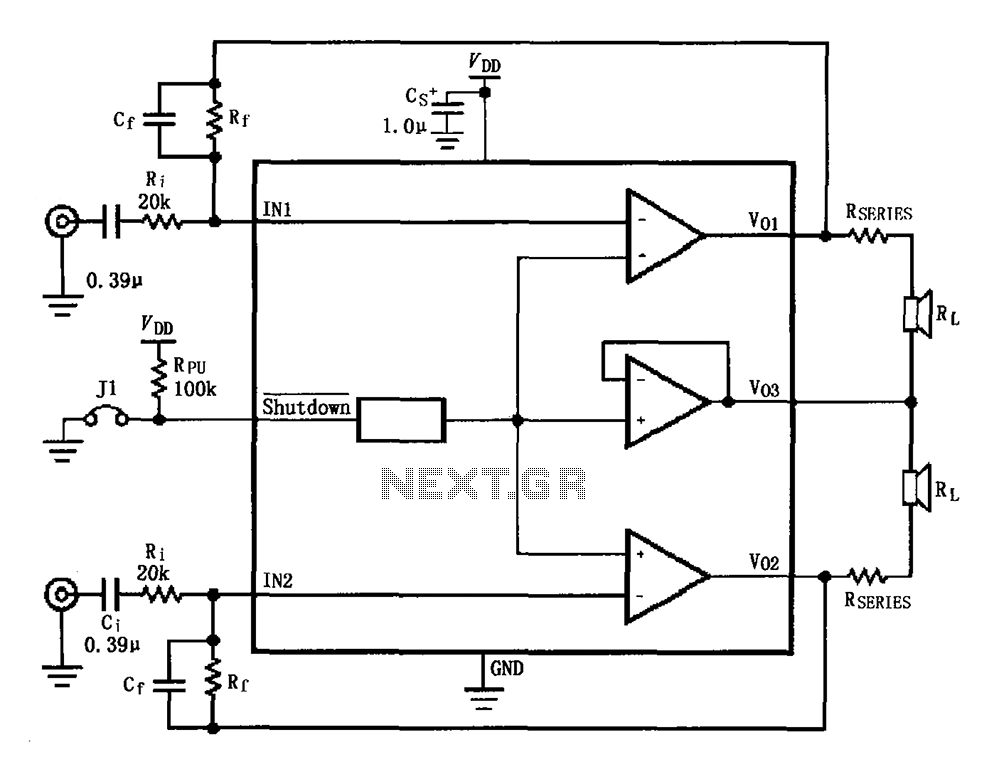
Description: The circuit for the LM4910 is designed to minimize output noise and reduce power consumption. The output noise is attenuated by utilizing a resistor in series with the load. A feedback resistor Rf is used in conjunction with a frequency bypass capacitor Cf to suppress high-frequency noise. A short jumper J1 is included; when J1 is grounded, the amplifier enters shutdown mode, minimizing power consumption. When J1 is open (VDD high), the amplifier operates normally, with maximum power determined by the equation PDMAX = 4VDD²/2RL.
The LM4910 circuit configuration aims to enhance audio performance by minimizing noise and optimizing power efficiency. The series resistor connected to the output terminal serves as a low-pass filter, effectively reducing the amplitude of unwanted noise signals that may interfere with the desired audio output. The choice of resistance value is critical, as it directly influences the attenuation level of the output noise.
The feedback resistor Rf is paired with a bypass capacitor Cf to form a high-frequency noise suppression network. This configuration allows for the filtering of high-frequency components that could degrade audio quality. The capacitor Cf should be selected based on the desired cutoff frequency, ensuring effective suppression of noise while maintaining the integrity of the audio signal.
The inclusion of jumper J1 provides flexibility in power management. In shutdown mode, the amplifier's power consumption is significantly reduced, which is beneficial in battery-operated devices where energy efficiency is paramount. The transition from shutdown to active mode is controlled by the state of jumper J1; when connected to ground, the amplifier is disabled, and when left open, it operates at full capacity. The maximum power output of the amplifier is calculated using the formula PDMAX = 4VDD²/2RL, where VDD is the supply voltage and RL is the load resistance. This relationship highlights the importance of selecting appropriate values for both VDD and RL to achieve optimal performance from the LM4910 amplifier. As shown for the LM4910 minimum output noise/reduce the output power circuit. Reduce output noise measures are: between the output terminal of a resistor in series with the loa d Rseries, so that the output noise can be attenuated, to achieve the purpose of reducing noise; in parallel across the feedback resistor Rf frequency bypass capacitor Cf, with to suppress high frequency noise. J1 short jumper, when short jumper J1 is grounded, the amplifier is in shutdown mode, the power consumption to a minimum; when J1 short jumper off (VDD high), the amplifier is in working mode, the power PDMAX 4VDD2/2RL.
The LM4910 circuit configuration aims to enhance audio performance by minimizing noise and optimizing power efficiency. The series resistor connected to the output terminal serves as a low-pass filter, effectively reducing the amplitude of unwanted noise signals that may interfere with the desired audio output. The choice of resistance value is critical, as it directly influences the attenuation level of the output noise.
The feedback resistor Rf is paired with a bypass capacitor Cf to form a high-frequency noise suppression network. This configuration allows for the filtering of high-frequency components that could degrade audio quality. The capacitor Cf should be selected based on the desired cutoff frequency, ensuring effective suppression of noise while maintaining the integrity of the audio signal.
The inclusion of jumper J1 provides flexibility in power management. In shutdown mode, the amplifier's power consumption is significantly reduced, which is beneficial in battery-operated devices where energy efficiency is paramount. The transition from shutdown to active mode is controlled by the state of jumper J1; when connected to ground, the amplifier is disabled, and when left open, it operates at full capacity. The maximum power output of the amplifier is calculated using the formula PDMAX = 4VDD²/2RL, where VDD is the supply voltage and RL is the load resistance. This relationship highlights the importance of selecting appropriate values for both VDD and RL to achieve optimal performance from the LM4910 amplifier. As shown for the LM4910 minimum output noise/reduce the output power circuit. Reduce output noise measures are: between the output terminal of a resistor in series with the loa d Rseries, so that the output noise can be attenuated, to achieve the purpose of reducing noise; in parallel across the feedback resistor Rf frequency bypass capacitor Cf, with to suppress high frequency noise. J1 short jumper, when short jumper J1 is grounded, the amplifier is in shutdown mode, the power consumption to a minimum; when J1 short jumper off (VDD high), the amplifier is in working mode, the power PDMAX 4VDD2/2RL.
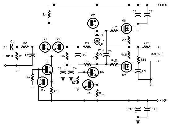
60 Watt MosFet Audio Amplifier
R1_47K 1/4W Resistor, R2_4K7 1/4W Resistor, R3_22K 1/4W Resistor, R4_1K 1/4W Resistor, R5, R12, R13_330R 1/4W Resistors, R6_1K5 1/4W Resistor, R7_15K 1/4W Resistor, R8_33K 1/4W Resistor, R9_150K 1/4W Resistor, R10_500R 1/2W Trimmer Cermet, R11_39R 1/4W Resistor, R14, R15_R33 2.5W Resistors,...
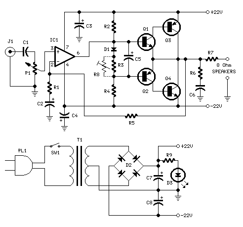
18w Audio Amplifier
18W audio amplifier constructed using transistors.
The 18W audio amplifier design utilizes a transistor-based configuration to achieve efficient amplification of audio signals. The circuit typically consists of several stages, including a preamplifier stage, a driver stage, and a power output stage....

LM 3875
The National Semiconductor's Overture series of integrated circuit (IC) audio amplifiers gained recognition due to the success of the 47 Laboratory's Gaincard amplifier, which utilizes the LM3875 chip from National Semiconductor. The Gaincard's simple design, low-cost components, and excellent quality-to-price...
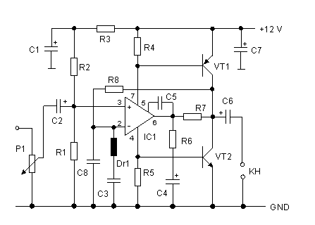
audio amplifier with NE592
The broadband amplifier NE592 can be used also for building a simple selective audio amplifier. By means of the +6 V and +12 V supply voltages, a DC coupling between the product detector and the AF amplifier is possible. The...
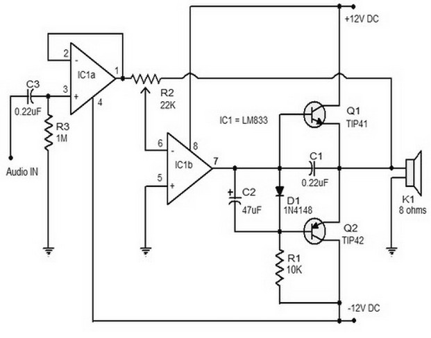
15w class b audio amplifie0r
The 15W Class B audio amplifier circuit presented here is a straightforward Class B audio amplifier utilizing the TL082 operational amplifier, along with TIP41 and TIP42 transistors. The LM833 is a dual amplifier known for its high scanning speed and...
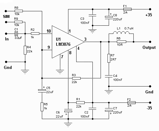
50watt audio power amplifier circuit
The amplifier drives a pair of speakers using two LM3876 amplifier chip circuits (50 watts per channel) or a pair of headphones with Meier Crossfeed through a clarifier and a dual OPA2134 Opamp. It features four selectable band inputs and...
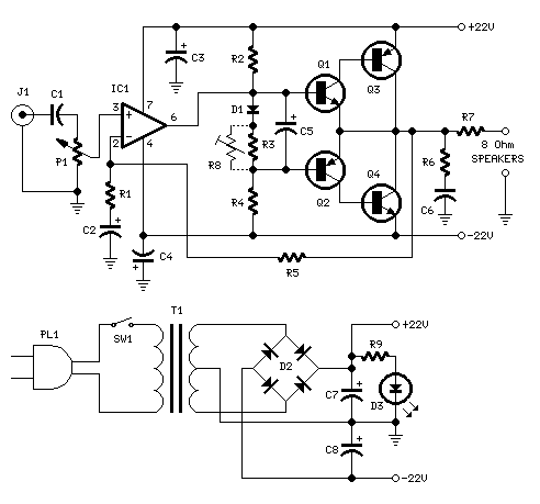
18W Audio Amplifier
High Quality very simple unit - No need for a preamplifier. Can be directly connected to CD players, tuners and tape recorders. Don't exceed 23 + 23V supply. Q3 and Q4 must be mounted on heatsink. D1 must be in...
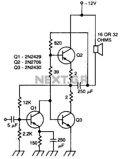
470 Mw complementary-symmetry audio amplifier
This circuit exhibits less than 2% distortion and maintains a flat response within 3 dB from 15 Hz to 130 kHz.
The described circuit is engineered to provide high fidelity audio performance, characterized by minimal distortion and a wide frequency response....
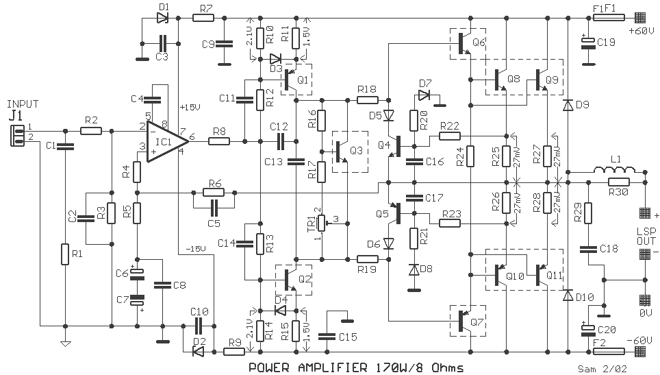
170 Watt audio amplifier
In the drawing, a simple but powerful power amplifier is presented. Its difference from classic designs, which use differential amplifiers in their input, is that this amplifier uses a complete NE5534 at its input. Thus, it is necessary to reduce...