


Low impedance pre amp circuit diagram
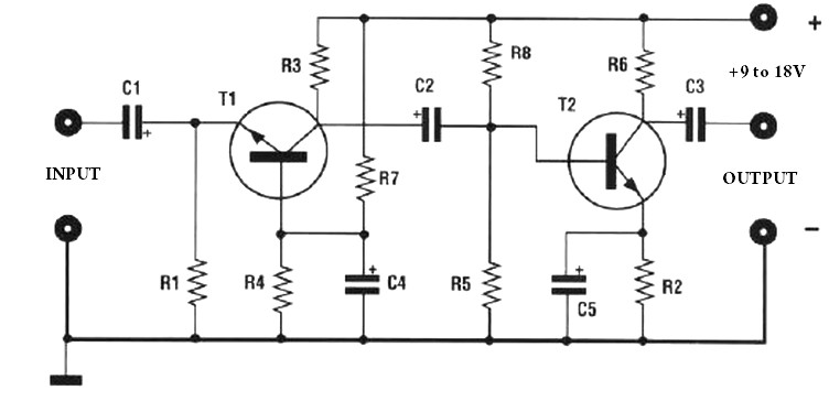
Description: The amplification of this preamplifier is very high. To reduce the amplification, a trimmer resistor R3 in series with a value of 100 ohms should be used. The system can be powered by a voltage ranging from 9 to 18 volts. For its implementation, refer to the provided circuit diagram layout.
The preamplifier circuit is designed to achieve high gain, making it suitable for applications requiring signal amplification from low-level sources. The use of a trimmer resistor (R3) allows for fine-tuning of the gain, providing flexibility in adjusting the amplification to meet specific requirements. The series configuration of R3 ensures that the gain can be decreased as needed, which is particularly useful in preventing saturation or distortion of the amplified signal.
Powering the circuit with a voltage supply between 9 and 18 volts offers versatility, allowing it to be integrated into various systems where different power supply voltages are available. This range provides sufficient headroom for the operational amplifier or transistor used in the preamplifier, ensuring optimal performance across different operating conditions.
The circuit layout should be followed closely to ensure proper functionality. It is essential to pay attention to the orientation of components, particularly polarized capacitors and diodes, as incorrect placement can lead to circuit failure. The layout should also consider minimizing noise and interference, which can be achieved through careful routing of signal and power traces, as well as grounding practices.
In summary, this preamplifier circuit is designed for high gain with adjustable output through a trimmer resistor and is capable of operating within a specified voltage range, making it a versatile choice for various electronic applications.The amplification of this pre amp is therefore very high, whether to reduce, there should be a trimmer R3 series to 100 ohms. The system can be powered by a voltage of between 9 and 18Volts. for its realization, follow the diagram layout.
The preamplifier circuit is designed to achieve high gain, making it suitable for applications requiring signal amplification from low-level sources. The use of a trimmer resistor (R3) allows for fine-tuning of the gain, providing flexibility in adjusting the amplification to meet specific requirements. The series configuration of R3 ensures that the gain can be decreased as needed, which is particularly useful in preventing saturation or distortion of the amplified signal.
Powering the circuit with a voltage supply between 9 and 18 volts offers versatility, allowing it to be integrated into various systems where different power supply voltages are available. This range provides sufficient headroom for the operational amplifier or transistor used in the preamplifier, ensuring optimal performance across different operating conditions.
The circuit layout should be followed closely to ensure proper functionality. It is essential to pay attention to the orientation of components, particularly polarized capacitors and diodes, as incorrect placement can lead to circuit failure. The layout should also consider minimizing noise and interference, which can be achieved through careful routing of signal and power traces, as well as grounding practices.
In summary, this preamplifier circuit is designed for high gain with adjustable output through a trimmer resistor and is capable of operating within a specified voltage range, making it a versatile choice for various electronic applications.The amplification of this pre amp is therefore very high, whether to reduce, there should be a trimmer R3 series to 100 ohms. The system can be powered by a voltage of between 9 and 18Volts. for its realization, follow the diagram layout.
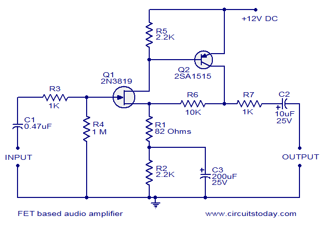
FET based audio preamplifier
This circuit is a low-noise audio preamplifier that utilizes one FET and one BJT. The audio signal to be amplified is connected to the base of FET Q1 through capacitor C1 and resistor R3. The base of transistor Q2 is...
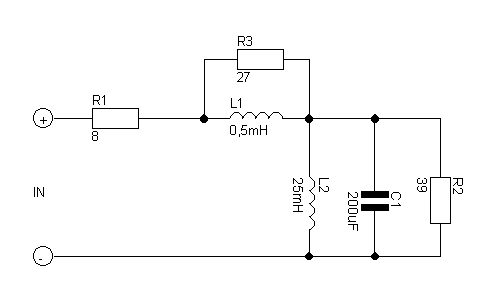
Audio power Amplifier Tester Dummy load
If you want to test an amplifier, a dummy load may be more convenient for speakers to use than actual speakers, due to noise or damage to the speakers. This circuit behaves in terms of impedance and frequency response as...
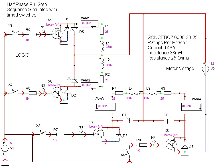
case stepper
Beige Bag Software has been offering affordable and innovative circuit design tools since 1990. B2 Spice provides schematics as well as analog, digital, and mixed-mode electronic circuit simulation. It integrates with EAGLE and CADSTAR PCB software.
B2 Spice is a powerful...
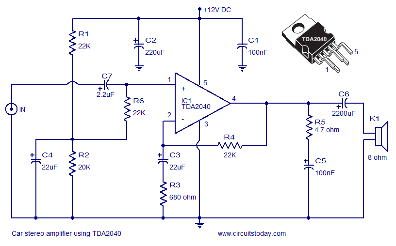
Car Amplifier Circuit Schematic using TDA2040 Integrated Audio Amplifier
A car stereo amplifier circuit utilizing the TDA2040 is presented here. The TDA2040 is a monolithic integrated audio amplifier that functions in Class AB mode. This integrated circuit features built-in short circuit protection and thermal shutdown capabilities, and it can...
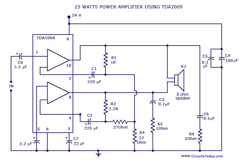
Power AmplifierCircuit and Schematics for 25 Watts-IC TDA2009
Power amplifier circuit diagram with schematics. This simple audio power amplifier circuit is designed for 25 watts output power using TDA 2009 IC, which has two channels (stereo), 12.5 W for each channel.
The described power amplifier circuit utilizes the TDA...
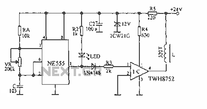
Audio vibration thaw circuit diagram
The device is designed to accelerate the defrosting process of fish, meat, and other foods by utilizing audio vibrations. This method allows for defrosting in warm water, significantly reducing the time required compared to conventional methods, while preserving the freshness...
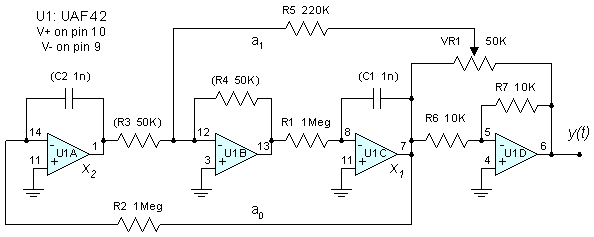
State Variable Oscillator
The major functional blocks necessary for designing a general-purpose audio oscillator are outlined, along with the details of the current prototype. The implementation is in the mode of an analog computer, as the desired outputs are sine and cosine values...
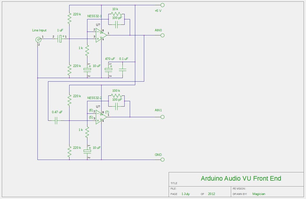
Audio VU meter with Extra wide Dynamic Range 69 dB using Arduino
After experimenting with a stereo version of the VU meter described in a previous blog post, a studio-grade VU meter is now being presented. This meter features 24 steps, spaced equally every 3 dB, and covers a wide dynamic range...
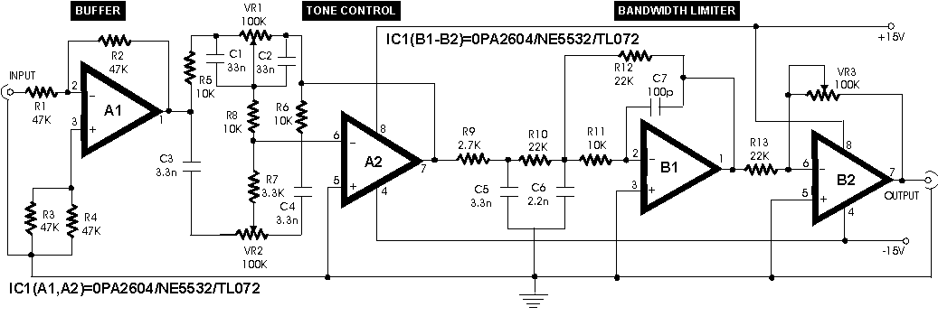
Audio Preamplifier circuit diagram with low distortion
In an audio amplifier, the quality of sound depends on several factors, including the quality of active and passive components, circuit configuration, and layout. The selection of components is influenced by the constructor's budget. Discrete active components like transistors have...