


Motorola Hi-Fi power amplifiers
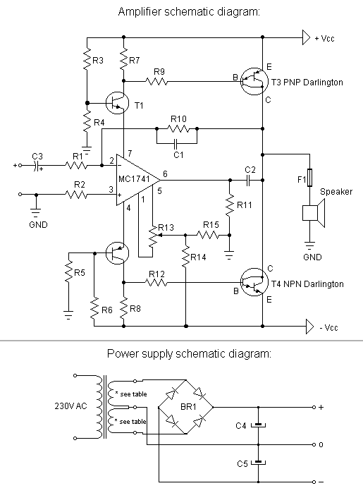
Description: This is a very simple, low-cost, Hi-Fi quality power amplifier. It can be built in five different configurations, as shown in the table, ranging from 20 W to 80 W RMS.
The Hi-Fi quality power amplifier circuit is designed to deliver high fidelity audio output while maintaining cost-effectiveness. The amplifier can be configured in five distinct ways to accommodate various power requirements, allowing for an output range from 20 watts to 80 watts RMS.
The core of the amplifier typically consists of a complementary push-pull output stage, which enhances efficiency and linearity, minimizing distortion while maximizing sound quality. The design may incorporate a voltage gain stage, often utilizing operational amplifiers or transistors, which can be adjusted based on the desired output power.
Input and output stages are crucial for the performance of the amplifier. The input stage may include capacitive coupling to block DC offset, ensuring only the AC audio signal is amplified. The output stage is designed to drive speakers effectively, with considerations for impedance matching to optimize power transfer and reduce signal loss.
Power supply requirements for this amplifier should be considered carefully. A regulated power supply may be necessary to ensure consistent performance and avoid fluctuations that could lead to distortion or clipping during high-demand audio peaks.
Thermal management is also an essential aspect of the design. Heatsinks may be employed to dissipate heat generated by the output transistors, ensuring reliable operation over extended periods.
Overall, this amplifier circuit not only provides versatility in output power configurations but also emphasizes high-quality sound reproduction, making it suitable for various audio applications, from home audio systems to small public address systems. Properly implemented, this design can deliver impressive audio performance while remaining accessible to hobbyists and professionals alike.This is a very simple, low cost, Hi-Fi quality power amplifier. You can build it 5 ways, like it?s shown in the table (from 20 W to 80 W RMS)..
The Hi-Fi quality power amplifier circuit is designed to deliver high fidelity audio output while maintaining cost-effectiveness. The amplifier can be configured in five distinct ways to accommodate various power requirements, allowing for an output range from 20 watts to 80 watts RMS.
The core of the amplifier typically consists of a complementary push-pull output stage, which enhances efficiency and linearity, minimizing distortion while maximizing sound quality. The design may incorporate a voltage gain stage, often utilizing operational amplifiers or transistors, which can be adjusted based on the desired output power.
Input and output stages are crucial for the performance of the amplifier. The input stage may include capacitive coupling to block DC offset, ensuring only the AC audio signal is amplified. The output stage is designed to drive speakers effectively, with considerations for impedance matching to optimize power transfer and reduce signal loss.
Power supply requirements for this amplifier should be considered carefully. A regulated power supply may be necessary to ensure consistent performance and avoid fluctuations that could lead to distortion or clipping during high-demand audio peaks.
Thermal management is also an essential aspect of the design. Heatsinks may be employed to dissipate heat generated by the output transistors, ensuring reliable operation over extended periods.
Overall, this amplifier circuit not only provides versatility in output power configurations but also emphasizes high-quality sound reproduction, making it suitable for various audio applications, from home audio systems to small public address systems. Properly implemented, this design can deliver impressive audio performance while remaining accessible to hobbyists and professionals alike.This is a very simple, low cost, Hi-Fi quality power amplifier. You can build it 5 ways, like it?s shown in the table (from 20 W to 80 W RMS)..
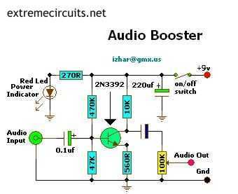
Mini Audio Booster Amplifier
This small amplifier circuit is ideal for boosting small audio units.
The small amplifier circuit is designed to enhance the audio signals from low-output devices, such as microphones or portable music players. It typically employs a transistor or an operational amplifier...
Power Amplifiers
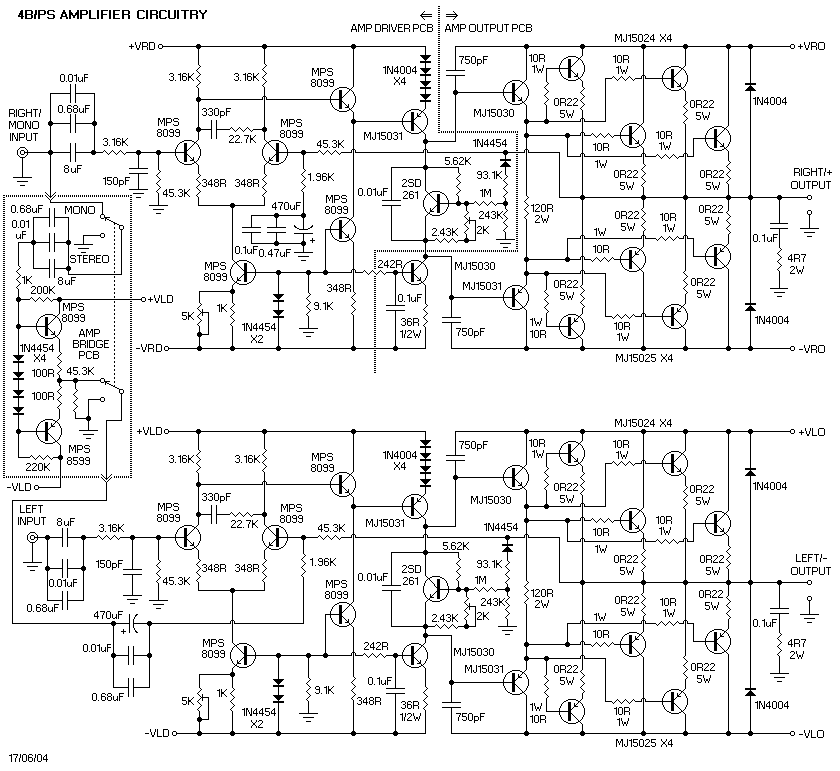
It is important to note that there is limited protection circuitry and fuses in this amplifier. A short turn-on delay for the output power supply is included to minimize thumps, along with a couple of line fuses, but no additional...
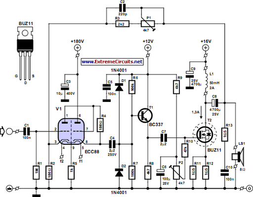
Simple Hybrid Audio Amplifier
The ongoing debate regarding the superiority of valves versus transistors is not the focus here. However, for those uncertain about their choice, this simple amplifier serves as an excellent experiment. The design employs a valve as a pre-amplifier and a...
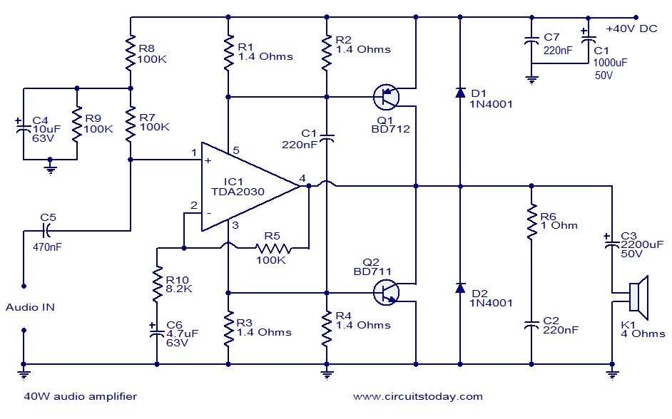
40W audio amplifier
This is a highly effective 40W power amplifier design utilizing the TDA2030 integrated circuit and two transistors. The circuit consists of only a few components and does not necessitate a dual power supply. The input signal is connected to the...
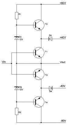
amplifier 1
A power amplifier is an amplifier designed to deliver maximum power output to a load. For example, in an audio system, it is the component responsible for driving speakers.
A power amplifier is a critical component in various electronic systems, particularly...
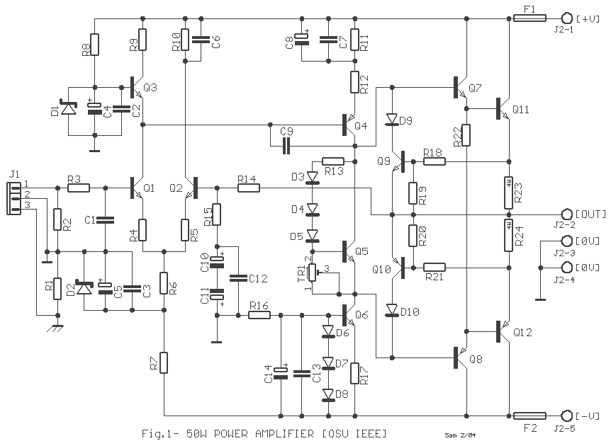
Power Amplifier 50W
Cleaned Input: This simple audio power amplifier was originally designed for a circuit board workshop, conducted by the OSU IEEE Student Group. At the workshop, 20 participants each constructed this amplifier, by etching and drilling the single sided circuit board,...
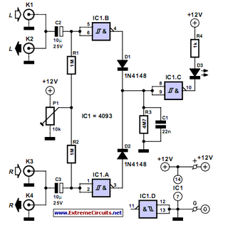
Simple Audio Peak Detector
This audio peak detector enables the monitoring of a pair of stereo channels using a single LED. The circuitry employed for both the left and right channels is identical.
The audio peak detector circuit is designed to provide a visual indication...

Audio Fader
In this circuit, Q1 serves as a simple amplifier with gain control provided by a variable emitter resistance supplied by FET Q2. When switch SI is in the up position, capacitor C3 discharges through resistor R5, resulting in a decrease...
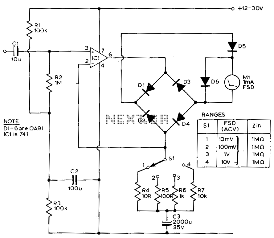
Audio-millivoltmeter
This circuit exhibits a flat frequency response from 8 Hz to 50 kHz, maintaining a -3 dB level at the 10 mV range. Furthermore, while the upper frequency limit remains consistent across less sensitive ranges, the lower frequency limit extends...