


Portable-amplifier
#FET op amp
#bipolar voltage
#gain calculation
#zero-set balance
#voltmeter
#potentiometer
#fixed resistors
#common ground
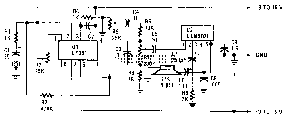
Description: The FET operational amplifier (op amp) requires a bipolar voltage at pins 4 and 7, with a common ground to achieve optimum gain. The gain can be calculated by dividing R2 by R1. Zero-set balance can be achieved through pins 1 and 5 using resistor R3. A voltmeter should be connected between pin 6 and ground, and R3 should be adjusted until the voltage reads zero. After establishing this condition, the ohmic resistance at each side of R3's center tap can be measured, allowing for the potentiometer to be replaced with fixed resistors. Additionally, resistors R6, R7, R5, and capacitor C3 form a tone control circuit that provides an option for bass boost if desired.
The FET op amp operates effectively with a bipolar power supply, which is essential for its functionality. The voltage levels at pins 4 and 7 must be carefully regulated to maintain the desired gain characteristics. The gain of the amplifier circuit is determined by the ratio of resistors R2 and R1, where a higher value of R2 relative to R1 results in increased gain.
To achieve zero-set balance, the adjustment of R3 is critical. This potentiometer is connected to pins 1 and 5, and by monitoring the voltage at pin 6 with a voltmeter, the balance can be finely tuned. The objective is to ensure that the voltage at pin 6 is maintained at zero volts, indicating that the op amp is operating at its optimal point. Once the adjustment is complete, replacing the potentiometer with fixed resistors based on the measured resistance values ensures stability and reliability in the circuit's performance.
Furthermore, the inclusion of resistors R6, R7, R5, and capacitor C3 forms a tone control section within the circuit. This configuration allows for the modification of the audio signal, specifically targeting bass frequencies. The arrangement can be adjusted to provide a bass boost, enhancing the overall audio output as needed. The selection of resistor and capacitor values will determine the cutoff frequency and the extent of the bass enhancement, allowing for customization based on user preferences or specific application requirements. This tone control feature is particularly useful in audio applications where sound quality and frequency response are critical.Ul, an FET op amp needs a bipolar voltage atpins 4 and 7 with a common ground for optimum gain. You can calculate the gain by dividing R2 by Rl. Zero-set balance can be had through pins i and 5 through R3. Put a voltmeter between pin 6 and ground and adjust R3 for zero voltage. Once you"ve established that, you can measure the ohmic resistance at each side of R3"s center tap and replace the potentiometer with fixed resistors. R6, R7, RS,and C3 forrn a tone control that will give you added bass boost, if needed;
The FET op amp operates effectively with a bipolar power supply, which is essential for its functionality. The voltage levels at pins 4 and 7 must be carefully regulated to maintain the desired gain characteristics. The gain of the amplifier circuit is determined by the ratio of resistors R2 and R1, where a higher value of R2 relative to R1 results in increased gain.
To achieve zero-set balance, the adjustment of R3 is critical. This potentiometer is connected to pins 1 and 5, and by monitoring the voltage at pin 6 with a voltmeter, the balance can be finely tuned. The objective is to ensure that the voltage at pin 6 is maintained at zero volts, indicating that the op amp is operating at its optimal point. Once the adjustment is complete, replacing the potentiometer with fixed resistors based on the measured resistance values ensures stability and reliability in the circuit's performance.
Furthermore, the inclusion of resistors R6, R7, R5, and capacitor C3 forms a tone control section within the circuit. This configuration allows for the modification of the audio signal, specifically targeting bass frequencies. The arrangement can be adjusted to provide a bass boost, enhancing the overall audio output as needed. The selection of resistor and capacitor values will determine the cutoff frequency and the extent of the bass enhancement, allowing for customization based on user preferences or specific application requirements. This tone control feature is particularly useful in audio applications where sound quality and frequency response are critical.Ul, an FET op amp needs a bipolar voltage atpins 4 and 7 with a common ground for optimum gain. You can calculate the gain by dividing R2 by Rl. Zero-set balance can be had through pins i and 5 through R3. Put a voltmeter between pin 6 and ground and adjust R3 for zero voltage. Once you"ve established that, you can measure the ohmic resistance at each side of R3"s center tap and replace the potentiometer with fixed resistors. R6, R7, RS,and C3 forrn a tone control that will give you added bass boost, if needed;
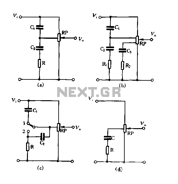
Using tap potentiometer loudness circuit
Figure 1.88 illustrates the loudness control circuit utilizing multiple taps on a potentiometer. In Figure (A), the connection is made between the tap and the potentiometer's input, along with the ground. An RC compensation network is employed, where the slide...
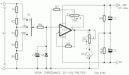
High Impedance DC Voltmeter using MOS Op-Amp
The circuit was designed to create a high-impedance voltmeter capable of measuring Direct Current (DC) voltages across various types of circuits.
The high-impedance voltmeter circuit typically employs operational amplifiers (op-amps) configured in a non-inverting arrangement to ensure minimal loading on the...
led display digital voltmeter
This is an easy-to-build yet highly accurate digital voltmeter designed as a panel meter for use in DC power supplies or any application requiring precise voltage indication. The circuit utilizes the CL7107 ADC (Analog to Digital Converter) IC manufactured by...
SINGLE CHIP DIGITAL VOLTMETER
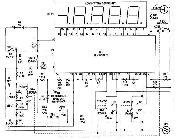
This 4.5-digit digital voltmeter (DVM) circuit is designed around the Maxim ICL7129ACPL analog-to-digital converter (A/D converter) and an LCD driver. It utilizes an ICL8069 CCZR 1.2-V band-gap reference diode for voltage referencing. The switch S2a-b-c allows the selection of one...
universal high resistance voltmeter
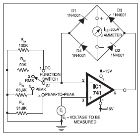
The full-scale deflection of the universal high-input-resistance voltmeter circuit depends on the position of the function switch. The term IFS in the equations refers to the meter's full-scale deflection current rating in amperes. It is important to note that neither...
software voltmeter
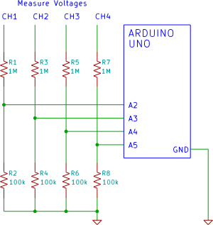
A four-channel voltmeter that displays voltage readings in a software application running on a computer. An Arduino reads the voltages and sends them to an application written in the Processing language.
The described circuit comprises a four-channel voltmeter system that utilizes...
Digital Voltmeter with ICL7129ACPL A/D converter
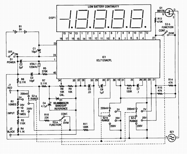
This 4 1/2-digit DVM circuit is built around a Maxim ICL7129ACPL A/D converter and LCD driver. An ICL8069 CCZR 1.2-V band-gap reference diode is used for a voltage reference. S2a-b-c select one of four ranges up to 200 V (maximum)....
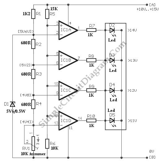
Voltmeter With LED For Car Battery
Below is a comparator circuit that can measure the voltage of a car battery in steps of 1 volt. The voltage indication is achieved through comparison.
The comparator circuit designed for measuring the voltage of a car battery utilizes an operational...
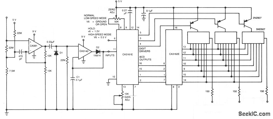
AC VOLTMETER
The CA081 and CA3140 BiMOS operational amplifiers provide minimal loading on the circuits being measured. The wide bandwidth and high slew rate of the CA081 enable the meter to operate at frequencies up to 0.5 MHz.
The CA081 and CA3140 are...