


simple audio amplifier
#transistor
#preamplifier
#2N2222
#2N2905A
#2N3053
#complementary symmetry
#audio amplification
#signal amplification
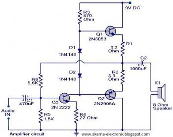
Description: The initial section of the circuit is a preamplifier that utilizes transistor Q1 (2N2222). The collector of transistor Q3 is connected to the base of transistor Q2 (2N2905A), which creates a complementary symmetry pair with Q3 (2N3053). The amplified signal can be accessed at the junction of the emitters of the two transistors.
The described circuit begins with a preamplifier stage that employs the 2N2222 transistor (Q1). This transistor serves as the input stage, amplifying weak signals before they are processed further. The configuration of Q1 allows for significant gain, which is crucial for improving the signal strength.
Transistor Q3 (2N3053) plays a critical role in this circuit as it is connected to the base of Q2 (2N2905A). This arrangement forms a complementary symmetry output stage, which is essential for driving the load effectively. The complementary pair configuration enhances the efficiency of the circuit by allowing for push-pull operation, where one transistor conducts during one half of the signal cycle while the other conducts during the opposite half. This results in improved linearity and reduced distortion in the output signal.
The output of the preamplifier can be obtained from the junction of the emitters of Q2 and Q3. This point serves as the amplified output, providing a stronger signal that can be fed into subsequent stages of the circuit, such as additional amplification or processing stages. The careful selection of transistors and their arrangement ensures optimal performance of the preamplifier, making it suitable for a variety of applications in audio and signal processing systems.The first part of the circuit here is a preamplifier consisting of transistor Q1(2N2222). The collector of the Q3 is coupled to the base of Q2 (2N2905A), which forms a complementary symmetry pair with Q3 (2N3053). The amplified signal is available at the junction of emitter of two transistors.
The described circuit begins with a preamplifier stage that employs the 2N2222 transistor (Q1). This transistor serves as the input stage, amplifying weak signals before they are processed further. The configuration of Q1 allows for significant gain, which is crucial for improving the signal strength.
Transistor Q3 (2N3053) plays a critical role in this circuit as it is connected to the base of Q2 (2N2905A). This arrangement forms a complementary symmetry output stage, which is essential for driving the load effectively. The complementary pair configuration enhances the efficiency of the circuit by allowing for push-pull operation, where one transistor conducts during one half of the signal cycle while the other conducts during the opposite half. This results in improved linearity and reduced distortion in the output signal.
The output of the preamplifier can be obtained from the junction of the emitters of Q2 and Q3. This point serves as the amplified output, providing a stronger signal that can be fed into subsequent stages of the circuit, such as additional amplification or processing stages. The careful selection of transistors and their arrangement ensures optimal performance of the preamplifier, making it suitable for a variety of applications in audio and signal processing systems.The first part of the circuit here is a preamplifier consisting of transistor Q1(2N2222). The collector of the Q3 is coupled to the base of Q2 (2N2905A), which forms a complementary symmetry pair with Q3 (2N3053). The amplified signal is available at the junction of emitter of two transistors.
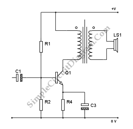
Transistor Class A Power Amplifier
The transistor is biased in Class A, meaning that the collector current flows continuously. This current can vary, increasing or decreasing in response to the input signal.
In a Class A biasing configuration, the transistor operates in the active region for...
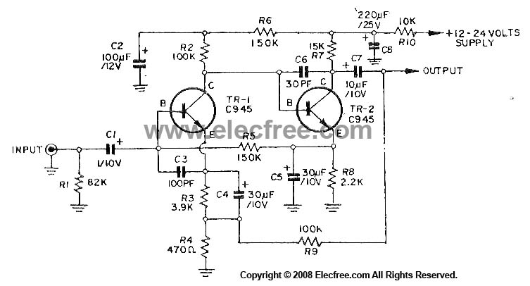
Dynamic Microphone Preamplifier using C945 transistor
This circuit utilizes three transistors (2SC945, 2C1815, or 2SC828) as the primary components, functioning as a typical low-noise transistor amplifier. It offers a gain of approximately 200 to 300 times and has a frequency response ranging from 50Hz to 100KHz....
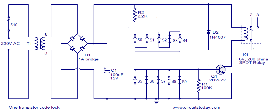
One 2N2222 Transistor Code Lock
The circuit consists of a basic transistor switch with a relay connected at its collector as the load. This represents a straightforward electronic code lock circuit that employs a single transistor.
The circuit operates by utilizing a transistor as a switch...
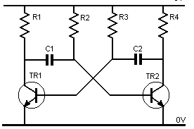
transistor astable multivibrator
Assume one of the transistors, TR1, becomes conductive initially. Under this condition, the collector-emitter voltage of TR1 should ideally be zero; however, it will be approximately 0.1 volts, while the base-emitter voltage is +0.6 volts. As a result, capacitor C1...
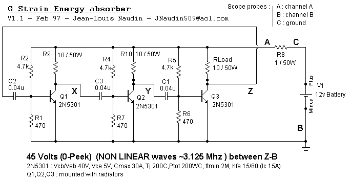
G STRAIN ENERGY ABSORBER
It is important to know that transistors Q1, Q2, Q3 must not work like an astable (tri-phase) multivibrator (you could verify it on scope (no square waves but NON LINEAR wave between XB, YB, ZB must be displayed on the...
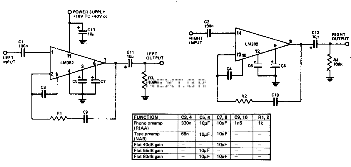
General purpose preamplifier
Limited information is available regarding the operation of the LM382, as the majority of its circuitry is integrated within the IC. Most components responsible for frequency determination are located on the chip, with only capacitors being externally mounted. The LM382...
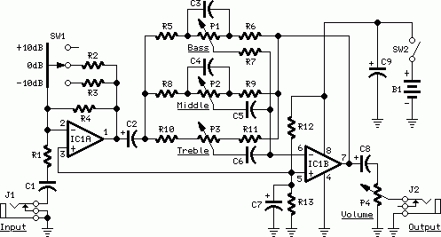
Guitar Control
Stand-alone, 9V battery powered unit, three-level input selector, three-band tone control. This preamplifier was designed as a stand-alone portable unit.
The described preamplifier is a compact, battery-operated device that operates on a 9V power supply, making it suitable for portable applications....
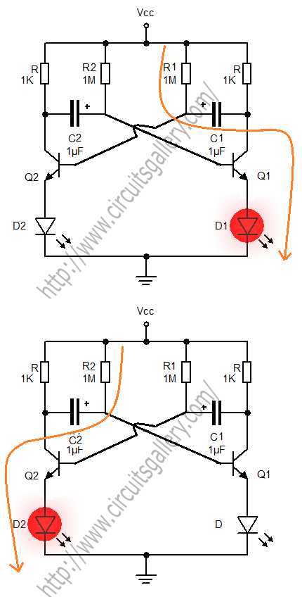
Astable Multivibrator
A transistorized astable multivibrator is a cross-coupled transistor network capable of generating a continuous square wave. It operates as a free-running oscillator or a regenerative switching circuit that utilizes positive feedback. The astable multivibrator continuously alternates between its two unstable...
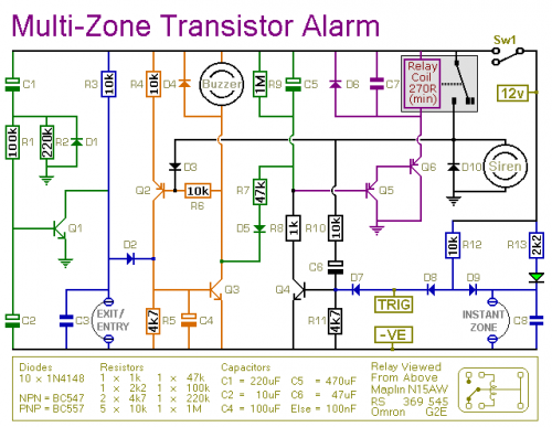
An Expandable Transistor Based Burglar Alarm
This transistor-based alarm system includes automatic exit and entry delays, a timed bell cut-off, and a system reset feature. In addition to the exit/entry zone, the basic alarm board is equipped with one instant zone, which is sufficient for many...