


tda2030a amplifier circuit used in home theaters
#TDA2030A
#audio amplifier
#home theater
#veroboard
#single supply
#bi-voltage
#output power
#datasheet
#beginner friendly
Description: This integrated circuit (IC) requires fewer external components, making it simpler for beginners to assemble it on a veroboard. The original circuit was sourced from its datasheet. A slightly modified version of the circuit is presented below. This circuit can operate with a single supply line; however, that configuration yields lower output power. Therefore, a bi-voltage topology is commonly employed. A supply of +/- 12V is needed. A 12-0-12 center-tapped step-down transformer can easily provide +12V and -12V. Additionally, since this IC does not necessitate a regulated supply, voltage can be directly supplied from the rectifier with the inclusion of just a capacitor.
The circuit design described utilizes an integrated circuit that is particularly advantageous for beginners due to its minimal external component requirements. The bi-voltage topology, which employs both positive and negative voltage supplies, enhances the output power capabilities of the circuit compared to a single supply configuration.
To implement this design, a 12-0-12 center-tapped transformer is essential. This transformer will provide the necessary voltage levels by producing +12V and -12V outputs. The center tap serves as the ground reference for the circuit, allowing for effective utilization of the bipolar power supply.
The rectification process involves converting the alternating current (AC) output from the transformer into direct current (DC). This can be achieved using a full-wave bridge rectifier, which is commonly employed for such applications. The output of the rectifier will be a pulsating DC voltage, which can be smoothed using a filter capacitor. The capacitor will help reduce voltage ripple, providing a more stable DC voltage for the IC.
It is important to note that the IC does not require a regulated power supply, which simplifies the design process. The unregulated output from the rectifier, combined with the filter capacitor, is sufficient for the IC's operation. This characteristic is particularly beneficial in applications where simplicity and ease of assembly are paramount.
Overall, this circuit design exemplifies an efficient and beginner-friendly approach to utilizing an integrated circuit with a bi-voltage power supply, leveraging readily available components to achieve desired performance outcomes.This IC require less external components too, making it easier for a beginner to make this on veroboard. The original circuit I got from it`s datasheet. A little modified circuit below, This can be operated with single supply line, but that topology gives less output power, hence this bi-voltage topology is used everywhere.
We need to provide +/- 12V to it. We can easily get +12V and -12V from a 12-0-12 CT step down transformer. And, as this IC doesn`t require regulated supply, we can feed voltage directly from rectifier with just a capacitor.
The circuit design described utilizes an integrated circuit that is particularly advantageous for beginners due to its minimal external component requirements. The bi-voltage topology, which employs both positive and negative voltage supplies, enhances the output power capabilities of the circuit compared to a single supply configuration.
To implement this design, a 12-0-12 center-tapped transformer is essential. This transformer will provide the necessary voltage levels by producing +12V and -12V outputs. The center tap serves as the ground reference for the circuit, allowing for effective utilization of the bipolar power supply.
The rectification process involves converting the alternating current (AC) output from the transformer into direct current (DC). This can be achieved using a full-wave bridge rectifier, which is commonly employed for such applications. The output of the rectifier will be a pulsating DC voltage, which can be smoothed using a filter capacitor. The capacitor will help reduce voltage ripple, providing a more stable DC voltage for the IC.
It is important to note that the IC does not require a regulated power supply, which simplifies the design process. The unregulated output from the rectifier, combined with the filter capacitor, is sufficient for the IC's operation. This characteristic is particularly beneficial in applications where simplicity and ease of assembly are paramount.
Overall, this circuit design exemplifies an efficient and beginner-friendly approach to utilizing an integrated circuit with a bi-voltage power supply, leveraging readily available components to achieve desired performance outcomes.This IC require less external components too, making it easier for a beginner to make this on veroboard. The original circuit I got from it`s datasheet. A little modified circuit below, This can be operated with single supply line, but that topology gives less output power, hence this bi-voltage topology is used everywhere.
We need to provide +/- 12V to it. We can easily get +12V and -12V from a 12-0-12 CT step down transformer. And, as this IC doesn`t require regulated supply, we can feed voltage directly from rectifier with just a capacitor.
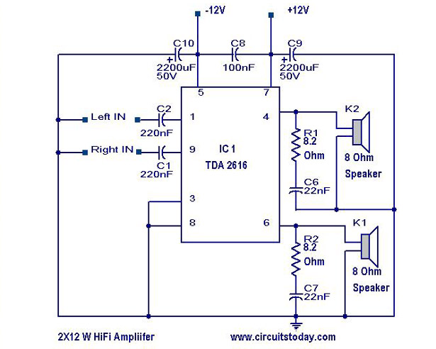
Hi Fi Amplifier Circuit 2X12 Watts
A simple Hi-Fi amplifier circuit diagram with a schematic for creating an audio amplifier, designed using the TDA 2616 integrated circuit (IC), which is a stereo power amplifier. It is suitable for use with radios, tape players, and televisions, delivering...
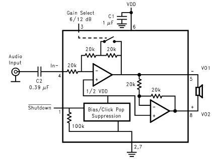
LM4096 audio amplifier circuit design
The LM4096 audio amplifier circuit diagram represents a straightforward audio amplifier capable of delivering a maximum output power of 1 watt, utilizing a minimal number of external electronic components. The LM4906, an audio power amplifier, is specifically engineered for demanding...
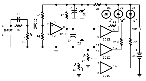
Three-Level Audio Power Indicator circuit
This circuit is designed to indicate the power output level of any audio amplifier. It is simple, portable, and displays three power levels that can be set to any desired value.
The circuit operates by utilizing a combination of resistive voltage...
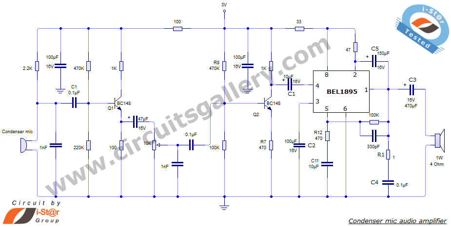
Condenser Microphone Amplifier Schematic using BEL 1895 IC
This document presents an audio amplifier circuit suitable for use in walkie-talkies, low-power transmitters, and packet radio receivers. The circuit utilizes a condenser microphone audio amplifier that delivers high-quality audio output of 0.5 watts at 3 volts. The design incorporates...
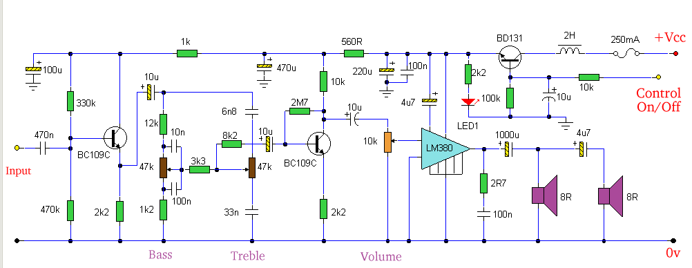
Amp with Tone Controls & Soft Switching
Amplifier with tone controls and soft switching. Notes: The soft switching is enabled by a BD131 transistor configured as a switch in an emitter follower arrangement. The collector is connected to a permanent load.
The described amplifier circuit incorporates tone controls...
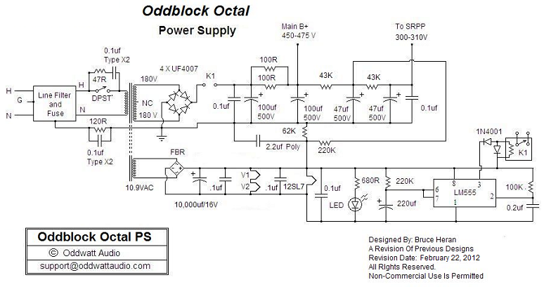
OddWatt Audio 5751 SRPP / KT88 Push-Pull Monoblock Tube Amplifier Kits
One of the advantages of hosting a hobby website is the opportunity to connect with individuals via email who share similar interests. Since posting Bruce's initial OddWatt project on the site, communication has occurred with numerous DIY hobbyists who have...
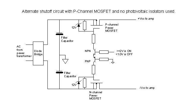
A DC Fault Protection Circuit for Audio Amplifiers
The standard Class AB audio power amplifier allows for direct coupling of the amplifier's output to speakers. This is beneficial as it eliminates capacitors or transformers that could compromise sound quality. The speakers are connected directly to the amplifying devices....
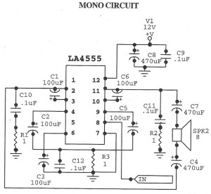
Audio Amplifier MonoCircuit With LA4555 IC
The following circuit illustrates an audio amplifier mono circuit diagram. This circuit is based on the LA4555 integrated circuit (IC). Features include a mono configuration and a power output of 2.3 watts.
The audio amplifier circuit utilizing the LA4555 IC is...
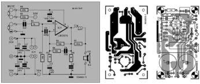
LM3876 - High-Performance 56W Audio Power Amplifier with Mute
The air-cored inductor L1 is constructed using 13 turns of 1mm diameter enamelled copper wire, featuring an inner diameter of 10mm. The completed inductor is positioned over R7, with its terminals soldered to those of the resistor. All electrolytic capacitors...