


TDA9302 Vertical deflection output schematics Schematic Diagram
#TDA9302H
#power amplifier
#vertical deflection
#television
#monitor
#display
#HEPTAWATTTM
#integrated circuit
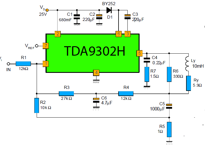
Description: The TDA9302H is a monolithic integrated circuit housed in a HEPTAWATTTM package. It functions as a high-efficiency power amplifier designed for direct drive vertical deflection coils in television yokes. This component is suitable for use in both color and black-and-white televisions, as well as in monitors and display systems.
The TDA9302H is engineered to enhance the performance of television and display systems by providing efficient power amplification for vertical deflection. The integrated circuit operates by driving the vertical yoke coils directly, which are responsible for controlling the vertical positioning of the electron beam in CRT-based displays. The high efficiency of the TDA9302H minimizes power loss, thereby improving the overall energy consumption of the device.
The HEPTAWATTTM package of the TDA9302H not only facilitates efficient heat dissipation but also ensures a compact form factor, making it suitable for integration into various electronic designs. The design of the TDA9302H includes internal protection features, such as thermal shutdown and overcurrent protection, which enhance the reliability and longevity of the circuit in demanding applications.
In terms of electrical characteristics, the TDA9302H typically operates within specific voltage and current ranges, allowing it to deliver optimal performance across a variety of operating conditions. The power amplifier is designed to achieve a high output current, which is essential for driving the vertical deflection coils effectively, ensuring stable and precise vertical scanning on the display.
Overall, the TDA9302H is a critical component for modern television and display technologies, providing robust performance and reliability in driving vertical deflection systems. Its integration in electronic designs contributes significantly to the quality and efficiency of visual displays.The TDA9302H is a monolithic integrated circuit in HEPTAWATTTM package. This is a high efficiency power amplifier for direct drive vertical rolls from the yokes of TV. This is intended to be used in Color and B & W television as well as in monitors and displays.
The TDA9302H is engineered to enhance the performance of television and display systems by providing efficient power amplification for vertical deflection. The integrated circuit operates by driving the vertical yoke coils directly, which are responsible for controlling the vertical positioning of the electron beam in CRT-based displays. The high efficiency of the TDA9302H minimizes power loss, thereby improving the overall energy consumption of the device.
The HEPTAWATTTM package of the TDA9302H not only facilitates efficient heat dissipation but also ensures a compact form factor, making it suitable for integration into various electronic designs. The design of the TDA9302H includes internal protection features, such as thermal shutdown and overcurrent protection, which enhance the reliability and longevity of the circuit in demanding applications.
In terms of electrical characteristics, the TDA9302H typically operates within specific voltage and current ranges, allowing it to deliver optimal performance across a variety of operating conditions. The power amplifier is designed to achieve a high output current, which is essential for driving the vertical deflection coils effectively, ensuring stable and precise vertical scanning on the display.
Overall, the TDA9302H is a critical component for modern television and display technologies, providing robust performance and reliability in driving vertical deflection systems. Its integration in electronic designs contributes significantly to the quality and efficiency of visual displays.The TDA9302H is a monolithic integrated circuit in HEPTAWATTTM package. This is a high efficiency power amplifier for direct drive vertical rolls from the yokes of TV. This is intended to be used in Color and B & W television as well as in monitors and displays.
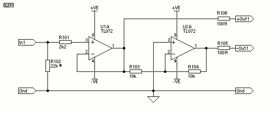
Bridging Adapter For Power Amplifiers
A stereo power amplifier is limited in its output power by two main factors - the impedance of the load and the internal power supply voltage. To obtain more power, one has very limited choices - other than the purchase...
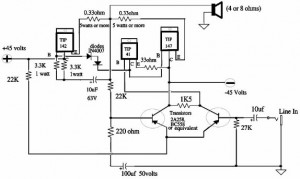
150W Power Amplifier
A 150W power amplifier circuit diagram utilizing power transistors TIP41, TIP142, and TIP147. The design is straightforward enough to construct without a printed circuit board (PCB). The power output range is approximately 100-150W.
The 150W power amplifier circuit is designed to...
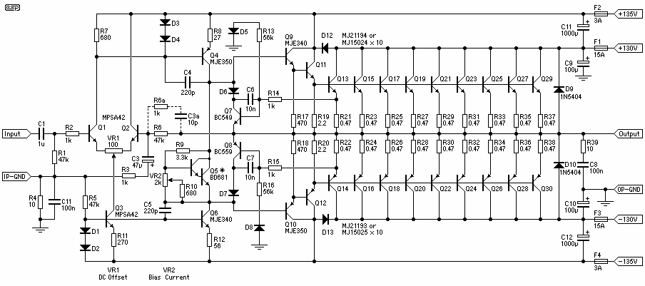
1,500W / 4 Ohms Power Amplifier
Cleaned Input: Capable of 2kW peak and a minimum of 1.5kW continuous, it has to be said that this amplifier will blow up any speaker connected to it. Regardless of the claimed power that various drivers can handle, they can't....
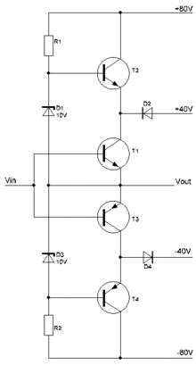
amplifier 1
A power amplifier is an amplifier designed to deliver maximum power output to a load. For example, in an audio system, it is the component responsible for driving speakers.
A power amplifier is a critical component in various electronic systems, particularly...
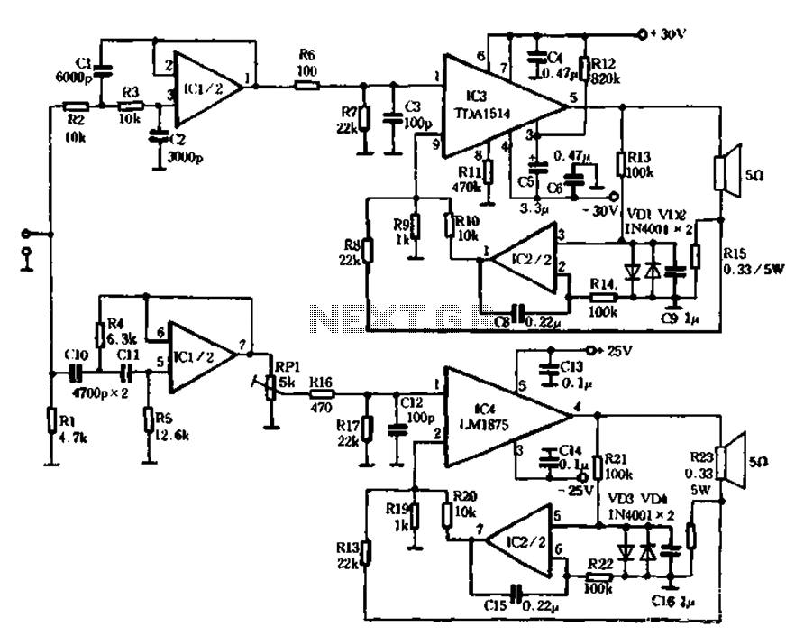
Current negative feedback electronic frequency power amplifier circuit
The mechanical and electrical schematic in Figure 5 illustrates a simple circuit comprising several components. The first component is an electronic crossover section utilizing the NE5532 operational amplifier, which is known as the "Emperor of the op-amp." This section forms...
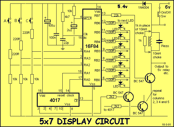
5x7 DISPLAY
You must be able to recognise components such as capacitors, diodes, zeners, transistors and resistors to build a 5x7 Display project. This information is covered in our BASIC ELECTRONICS course and a complete set of circuit symbols can be found...
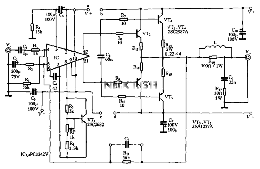
Compact 100W power amplifier circuit
The pLPC1342V and NE are two companies involved in a tube amplifier circuit utilizing 2SA1227A and 2SC2987A transistors, achieving a maximum output power of up to 120W with a cutoff frequency of up to 500 MHz. The circuit, illustrated in...
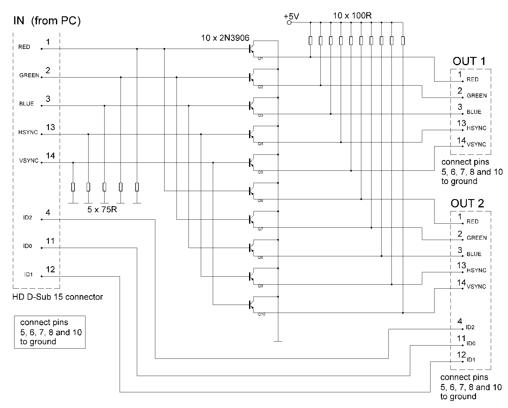
monitor splitter
The signal sources in the analog output stage of the PC SVGA card are designed to present the correct impedance of 75 ohms on each line, utilizing five resistors. The input impedances of the transistors are sufficiently high to avoid...
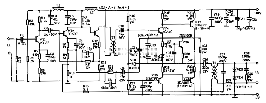
20W 40-500kHz PA 01
A 20W power amplifier circuit is illustrated in Figure 8-3. It features a pre-release level and enhances the power level through three stages to minimize significant phase shifts in the feedback loop. PNP silicon transistors are selected for both the...