


Video distribution amplifier
#video amplifier
#distribution amplifier
#NTSC
#LT1010
#signal isolation
#impedance matching
#video signal
#boost resistor
#gain-phase
#reflection isolation
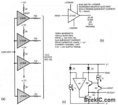
Description: The resistors in the output lines are used to isolate reflections from unterminated lines. If the line characteristics are known, the resistors can be removed. To satisfy NTSC gain-phase requirements, a small-value boost resistor is employed. Figures 3-27B and 3-27C illustrate the characteristics of the LT1010.
The circuit design incorporates resistors in the output lines primarily to mitigate signal reflections that can occur in unterminated transmission lines. This is crucial in high-frequency applications where impedance mismatches can lead to significant signal integrity issues. The use of resistors aids in damping these reflections, ensuring that the transmitted signal maintains its integrity over distance.
In scenarios where the characteristics of the transmission line are well understood, the output resistors may be omitted, allowing for a more straightforward circuit design without compromising performance. However, careful consideration must be given to the potential for reflections if the line is not properly terminated.
To comply with NTSC (National Television System Committee) gain-phase specifications, a small-value boost resistor is integrated into the circuit. This component is essential for maintaining the required signal levels and phase relationships, which are critical for proper video signal transmission.
The LT1010 operational amplifier is referenced in the context of this design, with Figures 3-27B and 3-27C providing graphical representations of its characteristics. The LT1010 is known for its high-speed performance and low distortion, making it suitable for applications requiring precise signal processing. Understanding its characteristics is vital for optimizing the overall circuit performance, particularly in video signal applications where fidelity is paramount.The resistors in the output lines are included to isolate reflections from unterminated lines. If the line characteristics are known, the resistors can be deleted. To meet NTSC gain-phase requirements, a small-value boost resistor is used. Figures 3-27B and 3-27C show the LT1010 characteristics.
The circuit design incorporates resistors in the output lines primarily to mitigate signal reflections that can occur in unterminated transmission lines. This is crucial in high-frequency applications where impedance mismatches can lead to significant signal integrity issues. The use of resistors aids in damping these reflections, ensuring that the transmitted signal maintains its integrity over distance.
In scenarios where the characteristics of the transmission line are well understood, the output resistors may be omitted, allowing for a more straightforward circuit design without compromising performance. However, careful consideration must be given to the potential for reflections if the line is not properly terminated.
To comply with NTSC (National Television System Committee) gain-phase specifications, a small-value boost resistor is integrated into the circuit. This component is essential for maintaining the required signal levels and phase relationships, which are critical for proper video signal transmission.
The LT1010 operational amplifier is referenced in the context of this design, with Figures 3-27B and 3-27C providing graphical representations of its characteristics. The LT1010 is known for its high-speed performance and low distortion, making it suitable for applications requiring precise signal processing. Understanding its characteristics is vital for optimizing the overall circuit performance, particularly in video signal applications where fidelity is paramount.The resistors in the output lines are included to isolate reflections from unterminated lines. If the line characteristics are known, the resistors can be deleted. To meet NTSC gain-phase requirements, a small-value boost resistor is used. Figures 3-27B and 3-27C show the LT1010 characteristics.
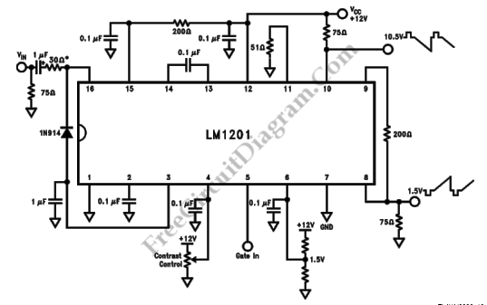
LM1201 Video Amplifier with Balanced (Bi-Phase) Output
This is a schematic diagram of a video amplifier circuit with bi-phase output. The bi-phase output generates both positive-going and negative-going signals, enabling balanced signaling. The primary component of this circuit is the LM1201. In this configuration, the inverted video...
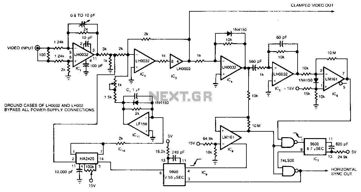
Video-signal-clamp
The circuit utilizes a track-and-hold amplifier in a closed-loop configuration to clamp the back-porch voltage of a standard video waveform to 0 V. The outputs of the circuit include a clamped composite video signal and a TTL-level horizontal blanking pulse....
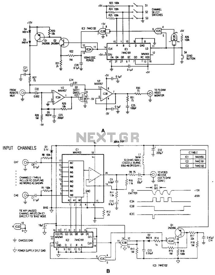
Video Signal Carrier Circuit
In the video system illustrated in Figures A and R, a single coaxial cable transmits power to a remote location, selects one of eight video channels, and returns the selected signal. This system can choose from several remote surveillance camera...
TV_video_signal_processor_circuit_1
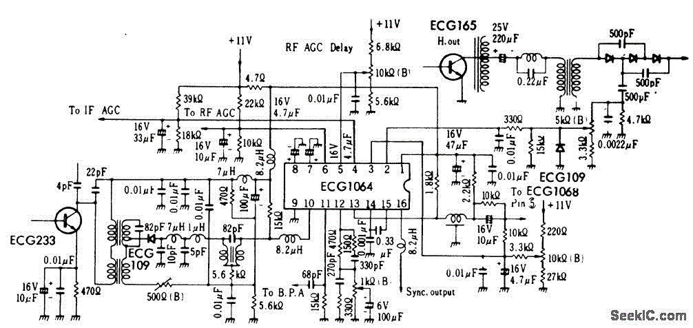
TV video signal processor circuit. The ECG1064 chip includes a primary video amplifier, two sync pulse amplifiers, a look-out protector, a noise detector, two noise gates, an automatic gain control (AGC) detector, an intermediate frequency (IF) AGC amplifier, a base...
Video Amplifier Circuit
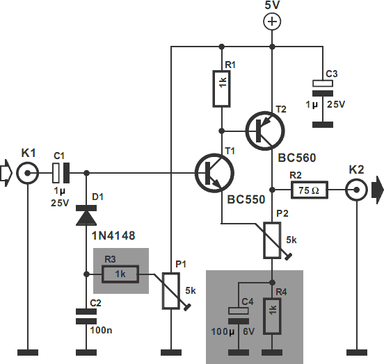
The video amplifier depicted in the diagram is a widely recognized design that is both simple and highly effective. However, the transistors are susceptible to damage if the potentiometers (black level and signal amplitude) are set to their extreme positions....
YUV/YCbCr to RGB converter
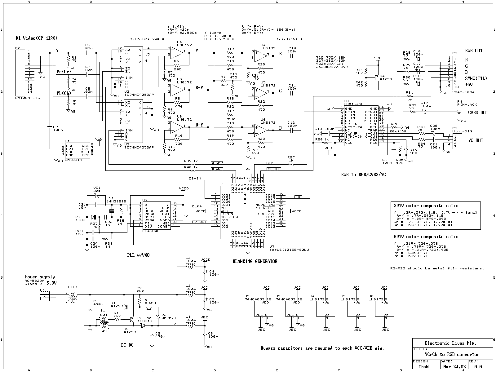
The device functions as a video recorder, DVD player, and TV game console, featuring a component video output. The component video signal resembles an RGB video signal; however, it is incompatible with RGB monitors.
The device's component video output is designed...
Video amplifier 1
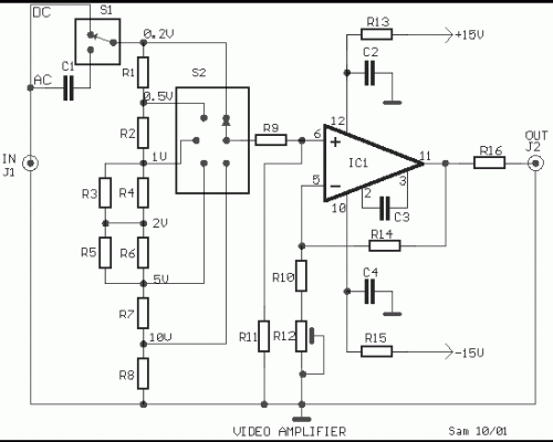
The objective is to enhance information transmission through the distribution of articles. For any issues related to article content, copyright, or other concerns, please reach out via email to [email protected] within 15 days. Prompt action will be taken to address...
Video-pulse-amplifier
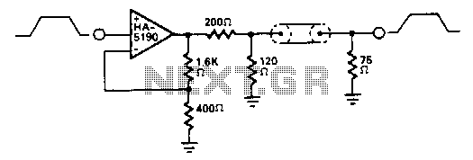
The HA-5190 can drive the 75-ohm coaxial cable with signals up to 2.5 V peak-to-peak without the need for current boosting. In this circuit, the overall gain is approximately unity due to the impedance matching network.
The HA-5190 is a high-performance...
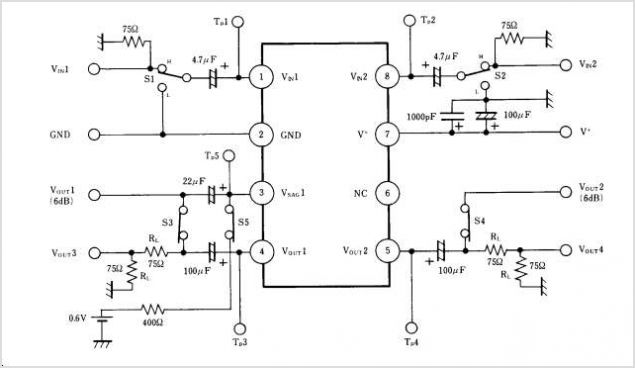
NJM2268 NJM2268 DUAL VIDEO 6dB AMPLIFIER
NJM2274AR is a sub-package of NJM2274A. For a detailed description, please refer to NJM2274A. The datasheet for NJM2274AR can be downloaded from the link below. Manufactured by New Japan Radio Co., Ltd.
The NJM2274AR is a component that serves as a...