


Wideband-500khz-1ghz-hybrid-amplifier
#wideband
#hybrid amplifier
#GaAs FET
#dual-gate
#transconductance
#series feedback
#power gain
#RF amplifier
#high frequency
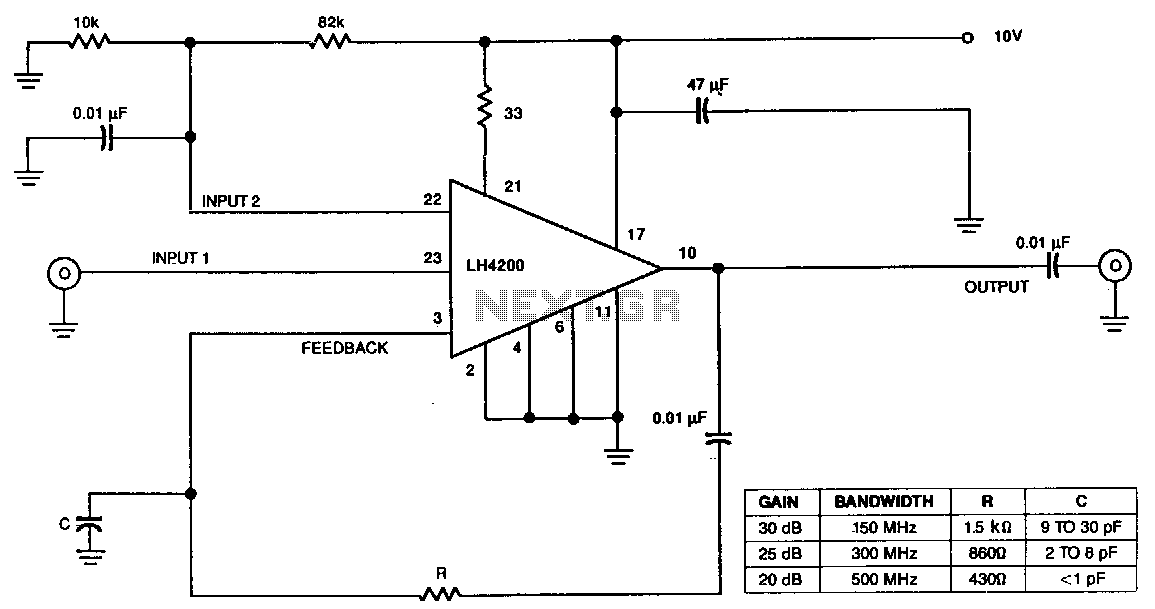
Description: The amplifier's input stage features a dual-gate GaAs FET, which offers low input capacitance and high transconductance. The first input accepts the signal, while the second input regulates the amplifier's gain. Additionally, there is a third input for series feedback. The output is connected to pin 3 through a single resistor that manages the overall power gain of the amplifier. At 10 MHz, the output can deliver 12 dBm into a 50-ohm load with 1 dB of signal compression. This AC-coupled amplifier exhibits a gain of 37 dB at 100 MHz and 3 dB at 1 GHz.
The described amplifier circuit utilizes a dual-gate Gallium Arsenide (GaAs) Field Effect Transistor (FET) in its input stage, which is essential for achieving high performance in RF applications. The low input capacitance of the FET minimizes signal distortion and allows for greater frequency response, making it suitable for high-frequency operations. The dual-gate configuration enhances the control over the gain, with the first gate receiving the input signal and the second gate serving as a gain control element. This arrangement allows for precise adjustments to the amplifier's performance based on the requirements of the application.
The inclusion of a third input for series feedback is a critical feature that enables the amplifier to maintain stability and linearity across its operating range. Feedback is provided through a resistor connected to pin 3, which plays a significant role in determining the overall power gain of the amplifier. By adjusting the resistance value, the designer can tailor the amplifier's gain characteristics to suit specific needs, ensuring optimal performance under varying conditions.
At a frequency of 10 MHz, the amplifier's output capability is noteworthy, delivering 12 dBm into a 50-ohm load while exhibiting only 1 dB of signal compression. This performance indicates that the amplifier can operate effectively without significant distortion, making it suitable for applications requiring high fidelity. The AC coupling in the amplifier design further enhances its versatility, allowing it to handle a wide range of input signal types.
The gain characteristics of the amplifier are impressive, with a gain of 37 dB at 100 MHz, which indicates strong amplification capabilities for signals in this frequency range. However, as the frequency increases to 1 GHz, the gain decreases to 3 dB, which is a common behavior in amplifiers due to factors such as parasitic capacitances and losses that become more pronounced at higher frequencies. This information is crucial for engineers when selecting the amplifier for specific applications, as it highlights the frequency-dependent nature of the amplifier's performance. Overall, the design and specifications of this amplifier make it a robust choice for high-frequency signal processing in various electronic applications.The amplifier"s input stage is a dual-gate GaAs FET, which provides low input capacitance and high transconductance. The dual-gate structure accepts the signal on input 1. Input 2 controls the gain of the amplifier. The amplifier has a third input for use in series feedback. The output feeds back to pin 3 via a single resistor, which controls the overall power gain of the amplifier.
At 10 MHz, the output is capable of delivering 12 dBm into a 50-0 load with 1 dB of signal compression. The ac-coupled amplifier has a gain of 37 dB at 100 MHz and 3 dB at 1 GHz.
The described amplifier circuit utilizes a dual-gate Gallium Arsenide (GaAs) Field Effect Transistor (FET) in its input stage, which is essential for achieving high performance in RF applications. The low input capacitance of the FET minimizes signal distortion and allows for greater frequency response, making it suitable for high-frequency operations. The dual-gate configuration enhances the control over the gain, with the first gate receiving the input signal and the second gate serving as a gain control element. This arrangement allows for precise adjustments to the amplifier's performance based on the requirements of the application.
The inclusion of a third input for series feedback is a critical feature that enables the amplifier to maintain stability and linearity across its operating range. Feedback is provided through a resistor connected to pin 3, which plays a significant role in determining the overall power gain of the amplifier. By adjusting the resistance value, the designer can tailor the amplifier's gain characteristics to suit specific needs, ensuring optimal performance under varying conditions.
At a frequency of 10 MHz, the amplifier's output capability is noteworthy, delivering 12 dBm into a 50-ohm load while exhibiting only 1 dB of signal compression. This performance indicates that the amplifier can operate effectively without significant distortion, making it suitable for applications requiring high fidelity. The AC coupling in the amplifier design further enhances its versatility, allowing it to handle a wide range of input signal types.
The gain characteristics of the amplifier are impressive, with a gain of 37 dB at 100 MHz, which indicates strong amplification capabilities for signals in this frequency range. However, as the frequency increases to 1 GHz, the gain decreases to 3 dB, which is a common behavior in amplifiers due to factors such as parasitic capacitances and losses that become more pronounced at higher frequencies. This information is crucial for engineers when selecting the amplifier for specific applications, as it highlights the frequency-dependent nature of the amplifier's performance. Overall, the design and specifications of this amplifier make it a robust choice for high-frequency signal processing in various electronic applications.The amplifier"s input stage is a dual-gate GaAs FET, which provides low input capacitance and high transconductance. The dual-gate structure accepts the signal on input 1. Input 2 controls the gain of the amplifier. The amplifier has a third input for use in series feedback. The output feeds back to pin 3 via a single resistor, which controls the overall power gain of the amplifier.
At 10 MHz, the output is capable of delivering 12 dBm into a 50-0 load with 1 dB of signal compression. The ac-coupled amplifier has a gain of 37 dB at 100 MHz and 3 dB at 1 GHz.
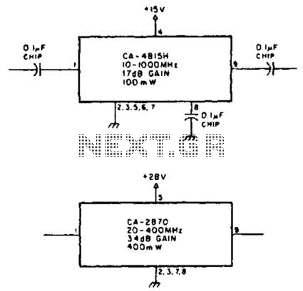
Wideband Power Amplifier Circuit
Using TRW part number CA-815H, a 17 dB gain amplifier capable of delivering 100 mW over a frequency range of 10 to 1000 MHz can be constructed. Additionally, the CA-2870 can provide 0.4 W with a gain of 34 dB...

2W RF Amplifier with MOSFET LF2810A
This is a 2W RF amplifier circuit built with the power MOSFET LF2810A. The schematic of the microstrip single-stage RF amplifier is shown in Figure A. The amplifier utilizes the M/A-Com LF2810A MOSFET, which is rated for a power output...
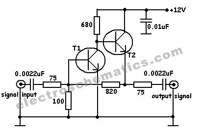
Simple Cable TV Amplifier Circuit
This cable TV amplifier circuit is an RF amplifier designed for quick installation between two coaxial cables. Both the input and output impedances are compatible with 75-ohm cables. The main amplifier is the T1 transistor, while T2 functions as an...
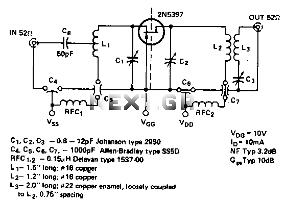
450Mhz-common-gate-amplifier
This is a low noise amplifier with a typical noise figure of 3 dB and approximately 10 dB of gain, operating within the frequency range of 450-470 MHz. It is designed for VHF two-way applications.
The described low noise amplifier (LNA)...
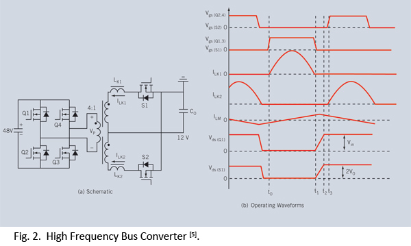
egan fet silicon power shoot out volume 10 high frequency resonant converters
Distributed power systems are commonly used in telecommunications, networking, and high-end server applications, utilizing a 48 V bus voltage derived from the telecom industry. This 48 V bus supplies several isolated point-of-load (POL) converters that power the end loads, with...
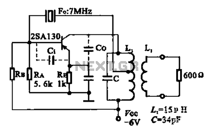
7MHz high frequency carrier oscillator
The 2SA130 transistor is used in an oscillator circuit with an oscillation frequency of 7 MHz. The power supply voltage is 6V, and the load is a frequency-selective resonant circuit with a quality factor of 600.
The circuit utilizes the 2SA130...
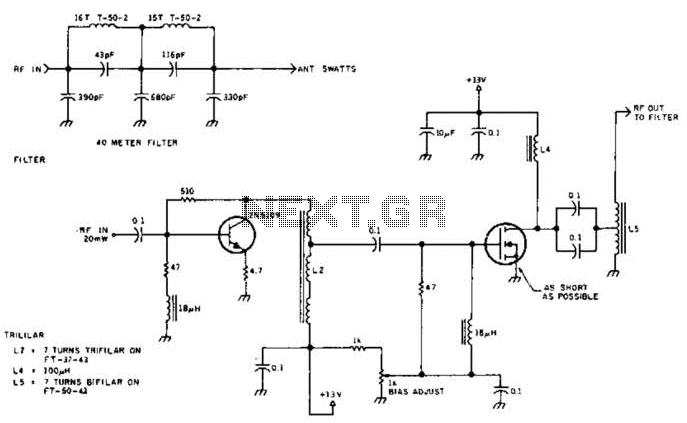
5W 7Mhz Rf Power Amplifier Circuit
The circuit illustrated is designed to generate up to 5 watts of RF output in the 40-meter (7 MHz) amateur band. The coils depicted are wound on toroidal cores from Armdon Associates Inc., with part numbers provided in the schematic....
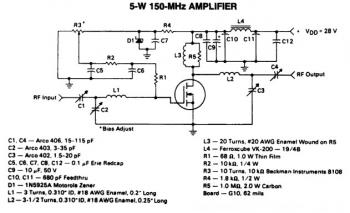
5w 150mhz rf amplifier circuit
This is a 5W -150MHz RF amplifier circuit that utilizes the MRF123 TMOSFET. The MRF123 is a high-gain FET which may exhibit instability at both VHF and UHF frequencies; therefore, a 68 Ohm input loading resistor is employed to improve...
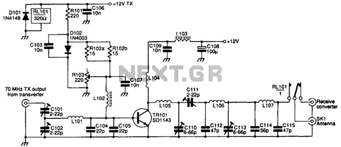
70Mhz Rf Power Amplifier Circuit
The SD1143 transistor offers a gain of approximately 14 dB in this circuit. Its design takes advantage of the fact that a 175-MHz device exhibits significantly higher gain when operated at lower frequencies. The amplifier was initially intended for use...