


Arduino Guitar Delay Pedal
#arduino
#guitar pedal
#delay circuit
#PT2399
#JFET preamp
#optoisolated
#audio processing
#signal filtering
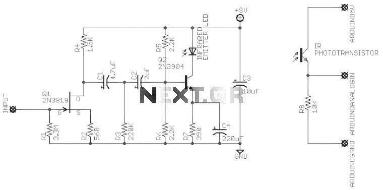
Description: An attempt at an Arduino guitar pedal. The guitar signal feeds through a PT2399 delay circuit, modified to include a JFET preamp phase. The delay circuit has Echo and Delay knobs. From there, it feeds into an optoisolated-Arduino-5V preamp, and out to the Arduino. The output from the Arduino is filtered and sent to the amp.
The described circuit involves several key components that work together to create a functional guitar pedal. The core of the circuit is the PT2399 delay chip, which is known for its ability to provide high-quality delay effects. This chip is configured to handle the incoming guitar signal, which is first processed through a JFET (Junction Field Effect Transistor) preamp. The JFET preamp serves to amplify the weak guitar signal before it enters the delay circuit, ensuring that the signal maintains its integrity and quality throughout the processing stages.
The delay circuit features two adjustable knobs, labeled Echo and Delay. The Echo knob controls the feedback level of the delayed signal, allowing the user to create various echo effects, while the Delay knob adjusts the time interval between the original and delayed signals. This flexibility enables musicians to tailor the sound to their preferences, providing a range of auditory experiences from subtle echoes to pronounced repeats.
After the delay processing, the signal is routed to an optoisolated Arduino-based preamp. The optoisolator serves to separate the guitar signal from the Arduino's control circuitry, preventing noise and interference from affecting the audio signal. The Arduino processes the incoming audio signal, which may involve additional effects or modifications programmed into the Arduino's firmware.
Finally, the output from the Arduino is filtered to remove any unwanted noise or artifacts before being sent to the amplifier. This filtering stage is crucial for maintaining sound quality, ensuring that only the desired audio frequencies are amplified. The overall design of this Arduino guitar pedal effectively combines analog and digital technologies, resulting in a versatile and innovative musical tool.An attempt at an Arduino guitar pedal. The guitar signal feeds through a PT2399 delay circuit, modified to include a JFET preamp phase. The delay circuit has Echo and Delay knobs. From there, it feeds into an optoisolated-Arduino-5V preamp, and out to the Arduino. The output from the Arduino is filtered and sent to the amp.
The described circuit involves several key components that work together to create a functional guitar pedal. The core of the circuit is the PT2399 delay chip, which is known for its ability to provide high-quality delay effects. This chip is configured to handle the incoming guitar signal, which is first processed through a JFET (Junction Field Effect Transistor) preamp. The JFET preamp serves to amplify the weak guitar signal before it enters the delay circuit, ensuring that the signal maintains its integrity and quality throughout the processing stages.
The delay circuit features two adjustable knobs, labeled Echo and Delay. The Echo knob controls the feedback level of the delayed signal, allowing the user to create various echo effects, while the Delay knob adjusts the time interval between the original and delayed signals. This flexibility enables musicians to tailor the sound to their preferences, providing a range of auditory experiences from subtle echoes to pronounced repeats.
After the delay processing, the signal is routed to an optoisolated Arduino-based preamp. The optoisolator serves to separate the guitar signal from the Arduino's control circuitry, preventing noise and interference from affecting the audio signal. The Arduino processes the incoming audio signal, which may involve additional effects or modifications programmed into the Arduino's firmware.
Finally, the output from the Arduino is filtered to remove any unwanted noise or artifacts before being sent to the amplifier. This filtering stage is crucial for maintaining sound quality, ensuring that only the desired audio frequencies are amplified. The overall design of this Arduino guitar pedal effectively combines analog and digital technologies, resulting in a versatile and innovative musical tool.An attempt at an Arduino guitar pedal. The guitar signal feeds through a PT2399 delay circuit, modified to include a JFET preamp phase. The delay circuit has Echo and Delay knobs. From there, it feeds into an optoisolated-Arduino-5V preamp, and out to the Arduino. The output from the Arduino is filtered and sent to the amp.
Maze Robot
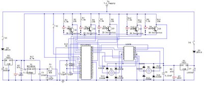
After completing the robot for the competition, updates to the blog were paused due to disappointment over not finishing the robot on time. An update on the progress made thus far is being provided. The motor driver was changed because...
Arduino Vocal Effects Box
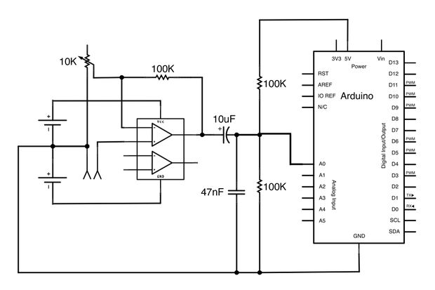
This Arduino-powered vocal effects box pitch shifts and distorts incoming audio signals to produce a wide variety of vocal effects. This project serves as an experiment with real-time digital signal processing using Arduino. It samples an incoming microphone signal at...
Auto-Fill Valve with Arduino
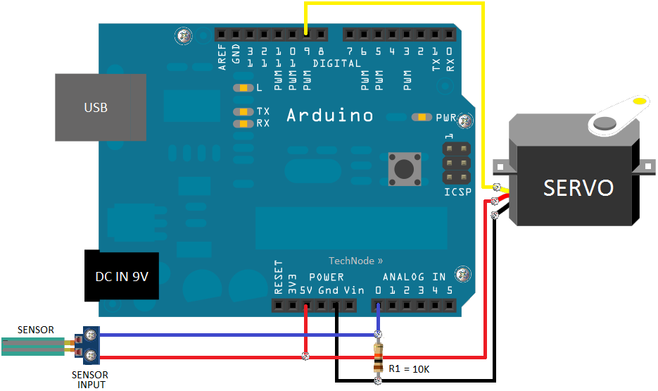
Part fill valves are commonly utilized in rainwater tanks. The valve activates when the water level in the tank drops to a low position.
Part fill valves play a crucial role in the management of water levels in rainwater harvesting systems....
Review of Arduino DAC solutions
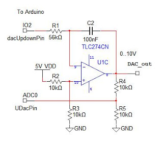
An analog output for Arduino can be achieved using a Digital-to-Analog Converter (DAC), commonly implemented with an R-2R ladder circuit. However, this DAC lacks an output buffer, which would enhance reliability and compatibility with various loads. For optimal performance, incorporating...
Ardurino Logger
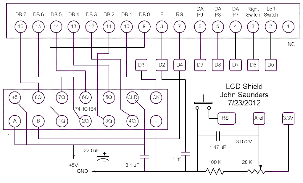
The switches and LEDs are mounted on the same front panel as the display, while the "D" connector is located at the rear. The two switches are momentary switches that activate downwards but latch upwards. Assorted components, such as single...
NONPRECISE PHANTASTRON VARIABLE DELAY
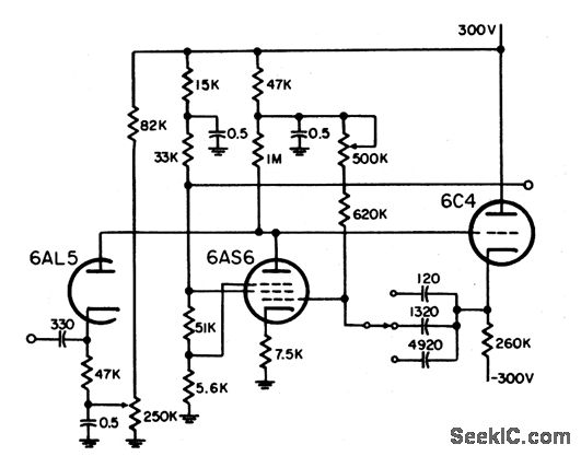
This circuit is designed to delay the start of the cathode ray tube (CRT) sweep for an expanded display. It offers three range settings: 0 to 5 miles, 60 miles, and 200 miles. The circuit primarily utilizes a cathode-coupled phantastron,...
Motor Driver works with PS not battery
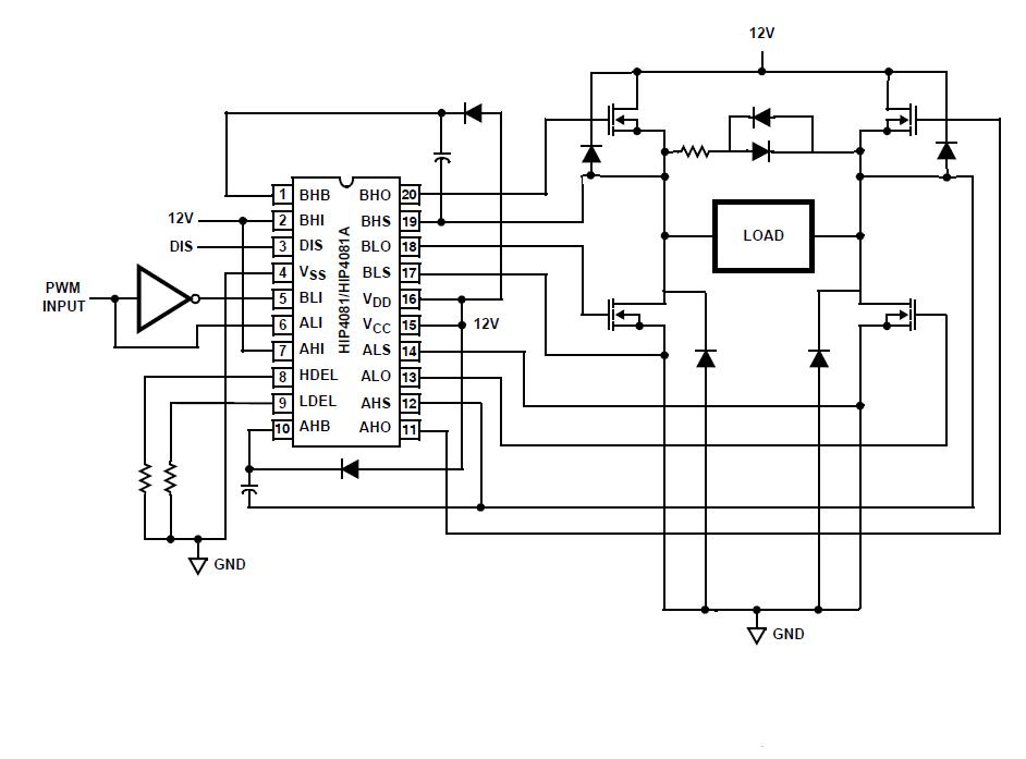
An individual is experiencing an unusual issue while utilizing an Intersil HIP4081A H-bridge driver integrated circuit (IC). The IC is connected to an Arduino microcontroller unit (MCU).
The Intersil HIP4081A is a high-performance H-bridge driver designed for driving DC motors and...
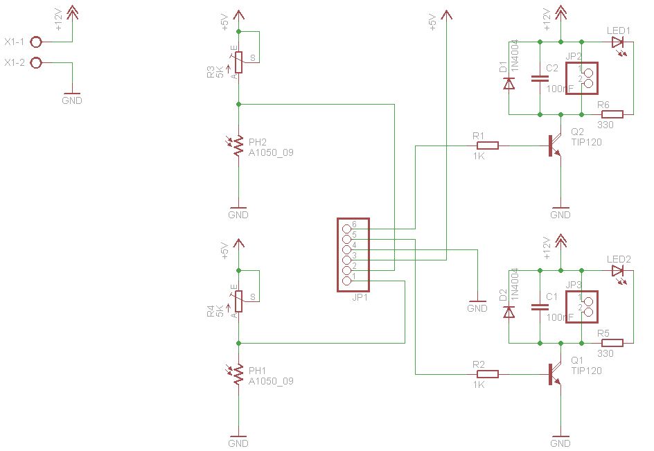
Light Follower Robot using Arduino
The figures above illustrate the fundamental concept of a robot, which comprises input and output devices connected to a central processing unit, often referred to as the brain. In this case, the Arduino acts as the brain, controlling all robotic...
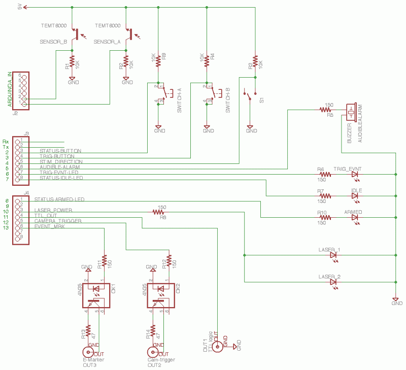
Arduino based camera trigger circuit
The core of the circuit features an Arduino microprocessor, represented by the header pins on the left side of the circuit schematic. Two analog inputs, labeled 0 and 1, are connected to the emitter sides of TEMT6000 ambient light sensors...