


DIY intervalometer for Sony NEX
#intervalometer
#Sony NEX
#time-lapse
#infrared LED
#Arduino
#camera control
#DIY
#photography
#serial LCD
#IR remote
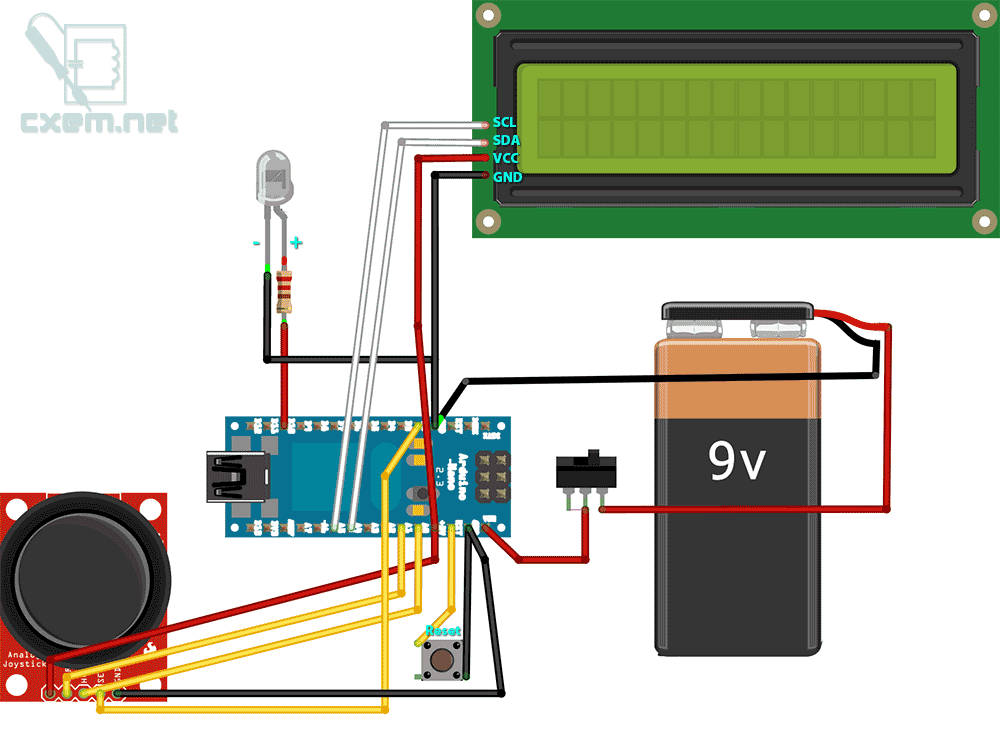
Description: A DIY intervalometer for the Sony NEX 5N camera designed for time-lapse photography. This intervalometer is compatible with most Sony cameras, including the NEX and Alpha series. The circuit utilizes an infrared LED and a Serial LCD with four outputs: GND, VCC, SDA, and SCL. The SDA (data) pin connects to Arduino Analog In 4, while the SCL (clock) pin connects to Analog In 5. The VCC pin connects to the 5V output of the Arduino, and GND connects to the GND of the Arduino. The circuit is powered by a 9V battery, with the positive terminal connected to the Vin input of the Arduino. The Arduino has a built-in 5V voltage regulator to power the Serial LCD. The anode of the infrared LED is connected through a current-limiting resistor to pin 10 of the Arduino, and the cathode is connected to GND.
The intervalometer setup involves an Arduino microcontroller interfacing with a Serial LCD and an infrared LED to control the camera shutter. The LCD is initialized with an I2C address of 0x27, supporting a 16x2 character display. The joystick module is utilized to adjust the interval between shots and to navigate the menu. The joystick's X-axis is connected to Analog 0, the Y-axis to Analog 1, and the Z-axis button to Digital 2 of the Arduino.
In the setup function, the pin modes are configured, and the LCD is initialized. The loop function continuously reads the joystick's position to determine user input. Depending on the joystick's position, the interval for capturing images can be adjusted. When the joystick button is pressed, the intervalometer enters a working mode where it captures images at the specified interval. The onboard LED provides visual feedback during operation.
The software includes functions to display the menu and the current working status on the LCD. The intervalometer can automatically turn off the LCD backlight after a specified duration of inactivity to conserve power. The code structure includes error handling for joystick inputs and ensures the interval remains within a valid range. The integration of the infrared LED allows for triggering the camera shutter remotely, making it suitable for time-lapse photography projects.A DIY intervalometer for my Sony NEX 5N camera so that I could do time-lapse photography. This intervalometer should work with most Sony cameras: NEX, Alpha and other. To work intervalometer used infrared LED Serial LCD has 4 output: GND, VCC, SDA, SCL. SDA (data) connect to Arduino Analog In 4, SCL (clock) connect to Analog In 5. Vcc connect to 5V Arduino, and GND connect to GND Arduino. Circuit is powered by 9V battery. Battery positive output connected to the input Vin Arduino. Arduino has a built-5V voltage converter that we need to power the Serial LCD. The anode of the IR LED is connected through current limiting resistor and connected to 10-pin Arduino. Cathode of the IR LED connected to GND. // Article // Version 1. 0 #include "Wire. h" #include "LiquidCrystal_I2C. h" #define axis_X 0 // axis X of Joystic connected to Analog 0 #define axis_Y 1 // axis Y of Joystic connected to Analog 1 #define axis_Z 2 // axis-button Z of Joystic connected to Digital 2 #define pinIRLED 10 // IR LED #define LEDgreen 13 // onboard LED #define autoOFF 10 // autoOFF backlight LCD LiquidCrystal_I2C lcd(0x27, 16, 2); // set the LCD address to 0x27 for a 16 chars and 2 line display int value_X, value_Y, value_Z = 0; // axis values int pos = 0; // current position (0 - delay, 1 - work) int interval = 1; // pause between shots (sec) int cntPict = 0; // shots count boolean working = false; unsigned long currentTime; unsigned long TimeShot, TimeLCDOff; void setup() { pinMode(axis_Z, INPUT); // Joystic button pinMode(pinIRLED, OUTPUT); // IR LED lcd.
init(); // init LCD lcd. backlight(); // turn LCD backlight ON lcd. clear(); // clear LCD show_menu(); // function show menu currentTime = millis(); TimeShot = currentTime; // shots timer TimeLCDOff = currentTime; // backlight timer //Serial. begin(115200); } void loop() { value_X = analogRead(axis_X); // read the analog value of the X axis value_Y = analogRead(axis_Y); // read the analog value of the Y axis value_Z = digitalRead(axis_Z); // read the digital value of the Z axis (button) value_Z = value_Z1; // invert the value if(working = false){ if(value_Y > 540){ // joystick up pos = 0; lcd.
backlight(); // LCD backlight ON TimeLCDOff = currentTime; // new value of TimeLCDOff show_menu(); } else if(value_Y < 500){ // joystick down pos = 1; lcd. backlight(); // LCD backlight ON TimeLCDOff = currentTime; // new value of TimeLCDOff show_menu(); } if(value_X > 530){ // joystick left lcd.
backlight(); // LCD backlight ON TimeLCDOff = currentTime; // new value of TimeLCDOff if(pos = 0){ -interval; if(value_X > 900) interval = interval-10; // joystick full left if(interval < 1) interval = 1; } show_menu(); } else if(value_X < 490){ // joystick right lcd. backlight(); // LCD backlight ON TimeLCDOff = currentTime; // new value of TimeLCDOff if(pos = 0) { +interval; if(value_X < 100) interval = interval+10; // joystick full right } show_menu(); } } if(value_Z = 1){ // joystick button press lcd.
backlight(); // LCD backlight ON TimeLCDOff = currentTime; if(working = true){ working = false; pos = 0; show_menu(); } if(pos = 1) show_working(); // turn on work mode } delay(200); currentTime = millis(); if(working = true){ if(currentTime >= (TimeShot + (interval*1000){ digitalWrite(LEDgreen, HIGH); // blink onboard LED delay(100); digitalWrite(LEDgreen, LOW); takePicture(); // send IR TimeShot = currentTime; +cntPict; // increase the counter shots show_working(); // refresh LCD } } if(currentTime >= (TimeLCDOff + (autoOFF*1000){ lcd. noBacklight(); // LCD backlight OFF } } void show_menu() { cntPict = 0; // zero out counter shots lcd.
clear(); lcd. setCursor(0, pos); lcd. print("*"); // current position lcd. setCursor(1, 0); lcd. print("delay:"); lcd. setCursor(8, 0); lcd. print(interval); lcd. setCursor(1, 1); lcd. print("go work"); } void show_working() { lcd. clear(); lcd. setCursor(3, 0);
The intervalometer setup involves an Arduino microcontroller interfacing with a Serial LCD and an infrared LED to control the camera shutter. The LCD is initialized with an I2C address of 0x27, supporting a 16x2 character display. The joystick module is utilized to adjust the interval between shots and to navigate the menu. The joystick's X-axis is connected to Analog 0, the Y-axis to Analog 1, and the Z-axis button to Digital 2 of the Arduino.
In the setup function, the pin modes are configured, and the LCD is initialized. The loop function continuously reads the joystick's position to determine user input. Depending on the joystick's position, the interval for capturing images can be adjusted. When the joystick button is pressed, the intervalometer enters a working mode where it captures images at the specified interval. The onboard LED provides visual feedback during operation.
The software includes functions to display the menu and the current working status on the LCD. The intervalometer can automatically turn off the LCD backlight after a specified duration of inactivity to conserve power. The code structure includes error handling for joystick inputs and ensures the interval remains within a valid range. The integration of the infrared LED allows for triggering the camera shutter remotely, making it suitable for time-lapse photography projects.A DIY intervalometer for my Sony NEX 5N camera so that I could do time-lapse photography. This intervalometer should work with most Sony cameras: NEX, Alpha and other. To work intervalometer used infrared LED Serial LCD has 4 output: GND, VCC, SDA, SCL. SDA (data) connect to Arduino Analog In 4, SCL (clock) connect to Analog In 5. Vcc connect to 5V Arduino, and GND connect to GND Arduino. Circuit is powered by 9V battery. Battery positive output connected to the input Vin Arduino. Arduino has a built-5V voltage converter that we need to power the Serial LCD. The anode of the IR LED is connected through current limiting resistor and connected to 10-pin Arduino. Cathode of the IR LED connected to GND. // Article // Version 1. 0 #include "Wire. h" #include "LiquidCrystal_I2C. h" #define axis_X 0 // axis X of Joystic connected to Analog 0 #define axis_Y 1 // axis Y of Joystic connected to Analog 1 #define axis_Z 2 // axis-button Z of Joystic connected to Digital 2 #define pinIRLED 10 // IR LED #define LEDgreen 13 // onboard LED #define autoOFF 10 // autoOFF backlight LCD LiquidCrystal_I2C lcd(0x27, 16, 2); // set the LCD address to 0x27 for a 16 chars and 2 line display int value_X, value_Y, value_Z = 0; // axis values int pos = 0; // current position (0 - delay, 1 - work) int interval = 1; // pause between shots (sec) int cntPict = 0; // shots count boolean working = false; unsigned long currentTime; unsigned long TimeShot, TimeLCDOff; void setup() { pinMode(axis_Z, INPUT); // Joystic button pinMode(pinIRLED, OUTPUT); // IR LED lcd.
init(); // init LCD lcd. backlight(); // turn LCD backlight ON lcd. clear(); // clear LCD show_menu(); // function show menu currentTime = millis(); TimeShot = currentTime; // shots timer TimeLCDOff = currentTime; // backlight timer //Serial. begin(115200); } void loop() { value_X = analogRead(axis_X); // read the analog value of the X axis value_Y = analogRead(axis_Y); // read the analog value of the Y axis value_Z = digitalRead(axis_Z); // read the digital value of the Z axis (button) value_Z = value_Z1; // invert the value if(working = false){ if(value_Y > 540){ // joystick up pos = 0; lcd.
backlight(); // LCD backlight ON TimeLCDOff = currentTime; // new value of TimeLCDOff show_menu(); } else if(value_Y < 500){ // joystick down pos = 1; lcd. backlight(); // LCD backlight ON TimeLCDOff = currentTime; // new value of TimeLCDOff show_menu(); } if(value_X > 530){ // joystick left lcd.
backlight(); // LCD backlight ON TimeLCDOff = currentTime; // new value of TimeLCDOff if(pos = 0){ -interval; if(value_X > 900) interval = interval-10; // joystick full left if(interval < 1) interval = 1; } show_menu(); } else if(value_X < 490){ // joystick right lcd. backlight(); // LCD backlight ON TimeLCDOff = currentTime; // new value of TimeLCDOff if(pos = 0) { +interval; if(value_X < 100) interval = interval+10; // joystick full right } show_menu(); } } if(value_Z = 1){ // joystick button press lcd.
backlight(); // LCD backlight ON TimeLCDOff = currentTime; if(working = true){ working = false; pos = 0; show_menu(); } if(pos = 1) show_working(); // turn on work mode } delay(200); currentTime = millis(); if(working = true){ if(currentTime >= (TimeShot + (interval*1000){ digitalWrite(LEDgreen, HIGH); // blink onboard LED delay(100); digitalWrite(LEDgreen, LOW); takePicture(); // send IR TimeShot = currentTime; +cntPict; // increase the counter shots show_working(); // refresh LCD } } if(currentTime >= (TimeLCDOff + (autoOFF*1000){ lcd. noBacklight(); // LCD backlight OFF } } void show_menu() { cntPict = 0; // zero out counter shots lcd.
clear(); lcd. setCursor(0, pos); lcd. print("*"); // current position lcd. setCursor(1, 0); lcd. print("delay:"); lcd. setCursor(8, 0); lcd. print(interval); lcd. setCursor(1, 1); lcd. print("go work"); } void show_working() { lcd. clear(); lcd. setCursor(3, 0);
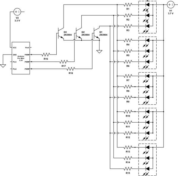
arduino leds in parallel switched with NPN transistors
It is noted that the LEDs are not configured in parallel with the transistor. If they were, the LEDs would illuminate when the transistor is off. Instead, the LEDs are connected in parallel before entering the transistor. The transistor only...
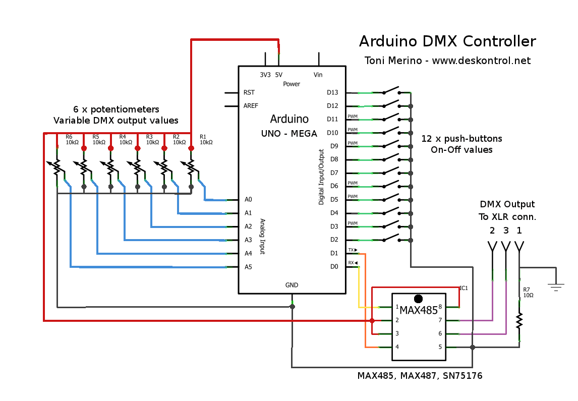
Small Arduino DMX controller
This document outlines the process of creating a compact and efficient Arduino DMX512 controller, which can be utilized to operate devices like a smoke machine via DMX or serve as testing equipment. The configuration includes six channels controlled by variable...
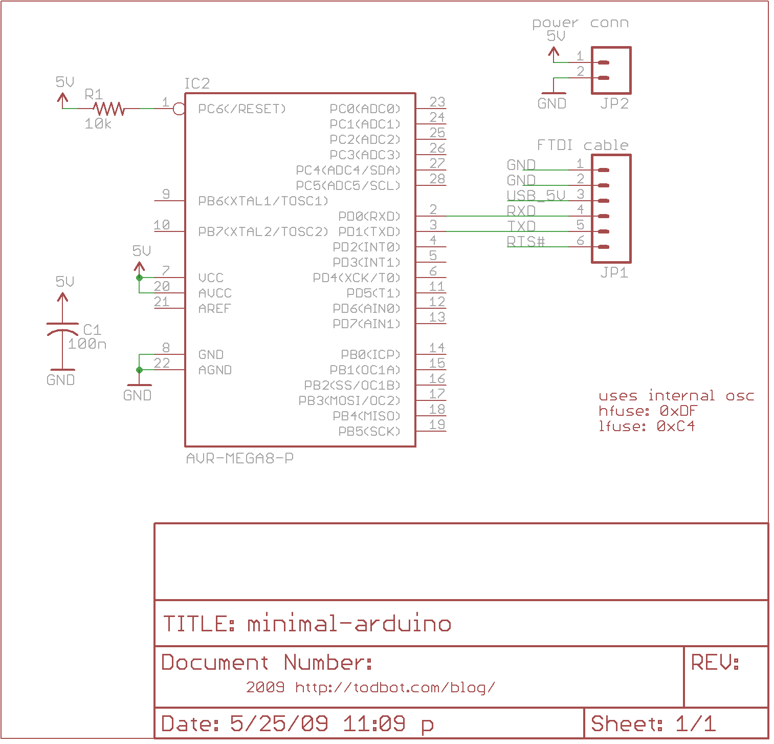
minimal arduino with atmega8
The minimal Arduino circuit is straightforward. It utilizes an internal 8MHz oscillator, similar to the Lilypad Arduino, but does not include a USB-to-serial interface. This functionality must be provided using an FTDI USB-to-serial cable or an older Arduino board. Although...
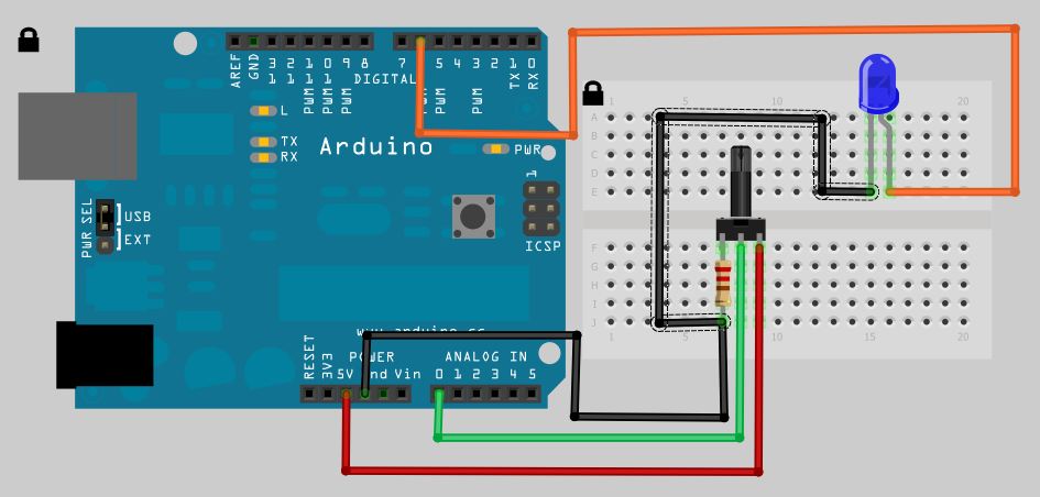
Arduino Analog Read Potentiometer to Digital Out LED
The analog to digital sketches have been extensively covered using various components. To progress to more complex circuits and concepts, it is essential to understand these simpler ones. This tutorial will not delve as deeply as others due to the...

message in a bottle
Message in a Bottle is an Arduino microcontroller and sensor project that enables an individual to record their voice inside a glass bottle and send it to someone else for playback. By uncorking the bottle and speaking into it, the...
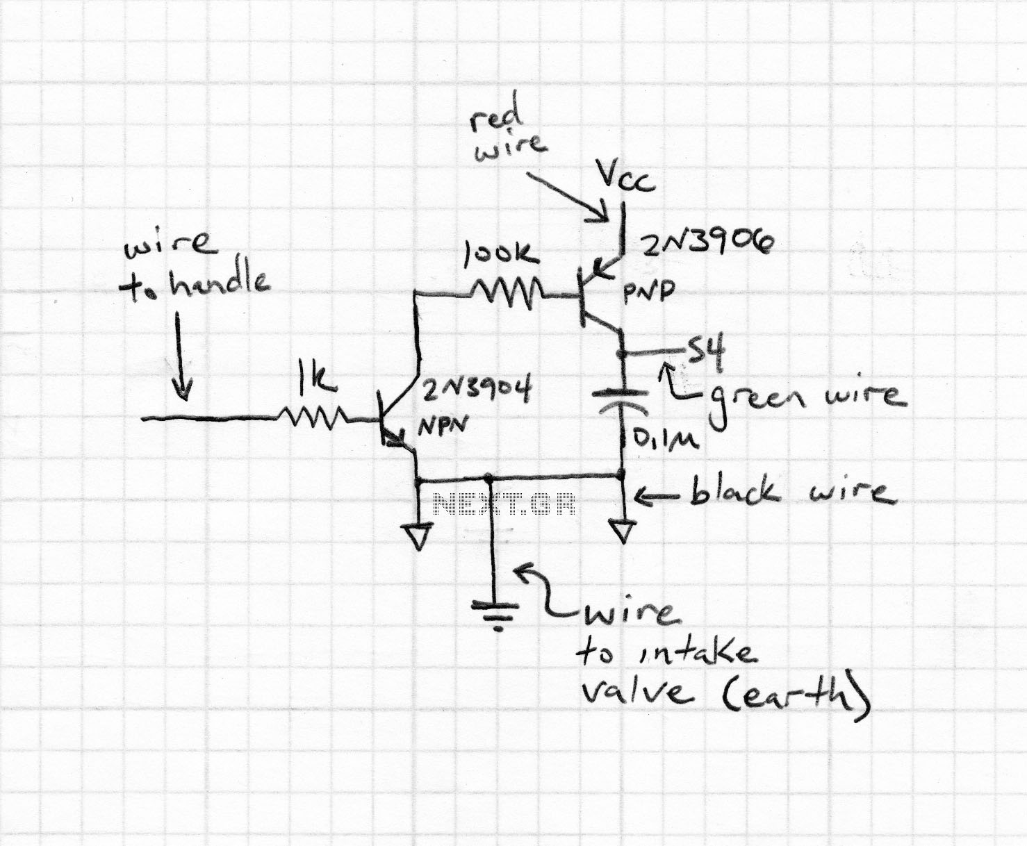
arduino intervalometer
An intervalometer for the Canon 400D camera has been developed. This device is based on an Arduino platform and utilizes code adapted from the creator of the Intervaluino project.
The intervalometer is a specialized electronic device designed to automate the process...
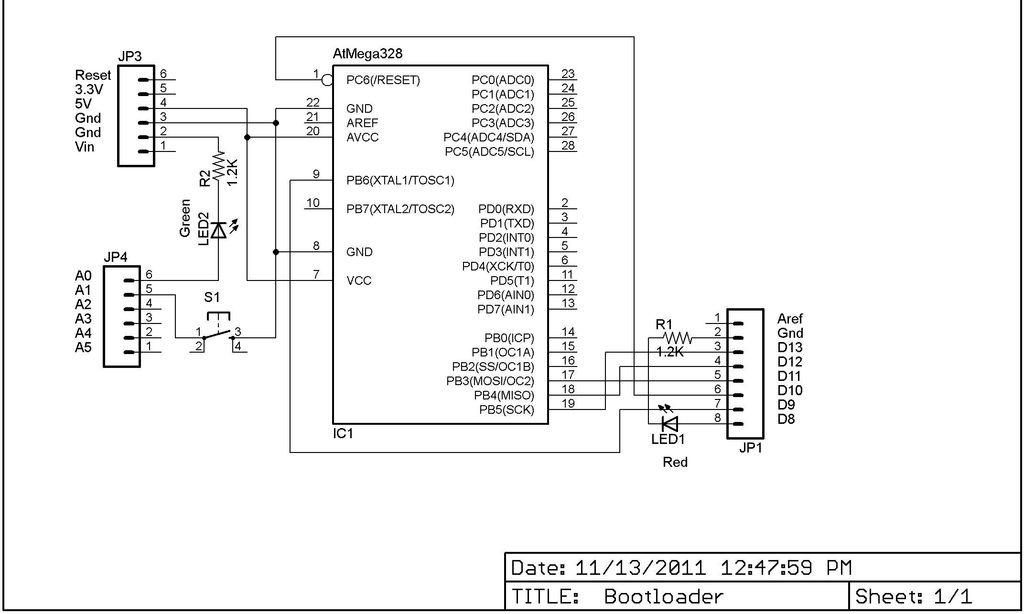
My Arduino In Circuit Programmer
This Lazy Old Geek is also an Arduino enthusiast. One of the common microcontrollers used by Arduinos is the Atmega328 chip. To utilize Arduino software, the Atmega must be equipped with bootloader software. There is a notable difference between the...
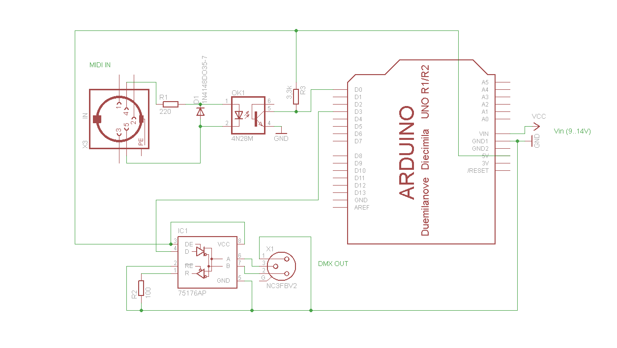
midi to dmx arduino control shield
A simple Arduino MIDI-to-DMX control was created for a robot band named Science Fiction Children. The setup consists of two inexpensive LED Par56 lights from Stairville, a basic DMX dimmer pack, and Ableton Live for sound management. The objective is...
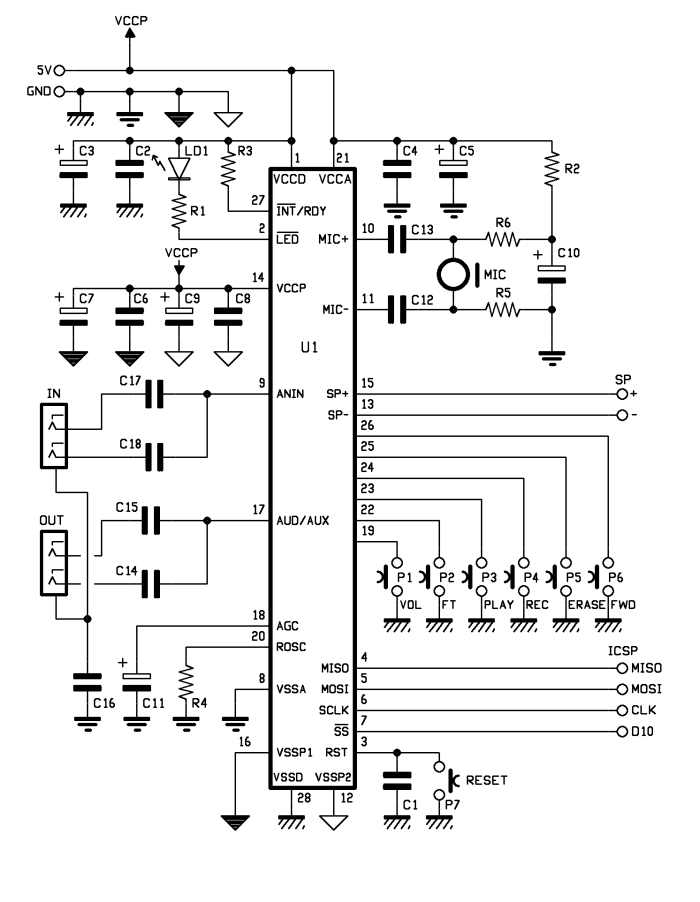
Voice Shield for Arduino
The aim of this project is to create an Arduino voice shield that facilitates numerous voice-related applications, primarily utilizing an integrated ISD1790PY chip. This voice and text-to-speech (TTS) functionality can be beneficial for integrating voice messages into alarm systems, implementing...