


Modular Music Box
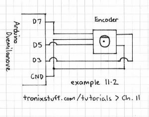
Description: The calculated value for the RSet resistor is approximately 17k ohms, although it should ideally be 28k ohms according to the data provided in the MV7744 datasheet, which specifies a forward voltage (Vf) of 2.1V and a forward current (If) of 20mA. It is important to note that these specifications apply to an LED matrix rather than individual LEDs. The Arduino Quadrature Encoder Library by Keith Neufeld is available for download, although initial compilation issues were encountered. Further instructions were found in the post to resolve these issues. Additionally, the intention is to utilize Christoph's DebounceButton Arduino library, which is currently unavailable, to implement functionalities such as onPress(), onRelease(), onHold(), and onClick(). This functionality, combined with the push button of the encoder, could serve as a hidden control system if necessary. A common ground is required for the I2C bus, as discovered by a colleague, Nick, and this will need to be incorporated into the circuitry of one of the boxes, likely the rotary sequencer. A significant challenge arises from the contact bounce of the buttons, which complicates the software suppression and direction determination of the rotation, leading to potential errors in the direction of the project sketch.
The circuit design involves the integration of a quadrature encoder, which provides two output signals (A and B) that indicate the direction and amount of rotation. The encoder's push button will be connected to a microcontroller, which will utilize the DebounceButton library to handle the button press events reliably. The RSet resistor is crucial for setting the correct current through the LEDs; thus, accurate calculations based on the intended application (individual LEDs versus an LED matrix) are necessary to avoid inconsistencies in brightness and performance.
Incorporating a common ground for the I2C bus is essential for ensuring stable communication between multiple devices. The rotary sequencer box will likely house both the encoder and the necessary circuitry to maintain this common ground. The design must account for the potential contact bounce from the encoder's push button, necessitating software debouncing techniques to ensure that only valid button presses are registered. This will involve implementing additional logic within the microcontroller's firmware to differentiate between actual button presses and noise caused by mechanical bouncing.
Furthermore, attention should be given to the power supply stability and noise filtering, especially in environments where multiple components share the same ground. Capacitors may be employed near the power pins of the microcontroller and the encoder to smooth out any fluctuations. Overall, careful consideration of the components, their specifications, and the interaction between them will lead to a robust and functional design for the intended application.I calculated the RSet resistor value at ~17k though it should probably have been 28k according to the table on the page (the MV7744 data sheet list Vf = 2. 1V and If = 20mA) but that`s for an LED matrix not individual LEDs happy for you to work out what this should be .
Used Keith Neufeld`s Arduino Quadrature Encoder Library available here to download and though initially it didn`t compile reading further in the post I came across instructions to add: Also intending to use quistoph`s DebounceButton Arduino library (link currently not working) to provide onPress(), onRelease, onHold(), onClick() functionality which combined with the push button of the encoder could be useful as a hidden` control system should we need it My colleague Nick discovered the requirements for a common ground for the I2C bus so we`ll need to plan this into the circuitry of one of the boxes probably the rotary sequencer The problem is first that they have a lot of contact bounce and trying to suppress this in software and determine the direction of rotation at the same time is a bit of a big ask and normally it won`t work. I don`t know if you noticed but some times the Project sketch would go in the wrong direction at times.
The circuit design involves the integration of a quadrature encoder, which provides two output signals (A and B) that indicate the direction and amount of rotation. The encoder's push button will be connected to a microcontroller, which will utilize the DebounceButton library to handle the button press events reliably. The RSet resistor is crucial for setting the correct current through the LEDs; thus, accurate calculations based on the intended application (individual LEDs versus an LED matrix) are necessary to avoid inconsistencies in brightness and performance.
Incorporating a common ground for the I2C bus is essential for ensuring stable communication between multiple devices. The rotary sequencer box will likely house both the encoder and the necessary circuitry to maintain this common ground. The design must account for the potential contact bounce from the encoder's push button, necessitating software debouncing techniques to ensure that only valid button presses are registered. This will involve implementing additional logic within the microcontroller's firmware to differentiate between actual button presses and noise caused by mechanical bouncing.
Furthermore, attention should be given to the power supply stability and noise filtering, especially in environments where multiple components share the same ground. Capacitors may be employed near the power pins of the microcontroller and the encoder to smooth out any fluctuations. Overall, careful consideration of the components, their specifications, and the interaction between them will lead to a robust and functional design for the intended application.I calculated the RSet resistor value at ~17k though it should probably have been 28k according to the table on the page (the MV7744 data sheet list Vf = 2. 1V and If = 20mA) but that`s for an LED matrix not individual LEDs happy for you to work out what this should be .
Used Keith Neufeld`s Arduino Quadrature Encoder Library available here to download and though initially it didn`t compile reading further in the post I came across instructions to add: Also intending to use quistoph`s DebounceButton Arduino library (link currently not working) to provide onPress(), onRelease, onHold(), onClick() functionality which combined with the push button of the encoder could be useful as a hidden` control system should we need it My colleague Nick discovered the requirements for a common ground for the I2C bus so we`ll need to plan this into the circuitry of one of the boxes probably the rotary sequencer The problem is first that they have a lot of contact bounce and trying to suppress this in software and determine the direction of rotation at the same time is a bit of a big ask and normally it won`t work. I don`t know if you noticed but some times the Project sketch would go in the wrong direction at times.
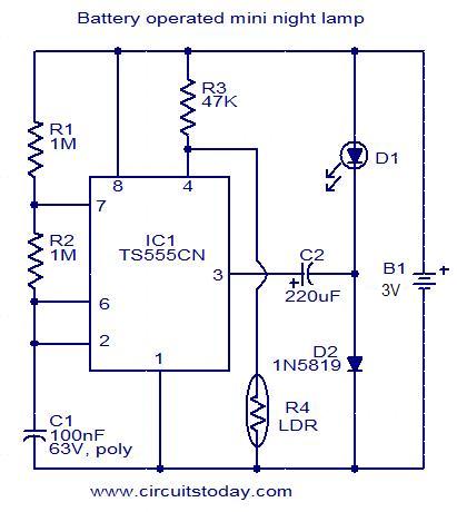
Battery operated mini night lamp
This circuit is designed as a low-power LED night lamp that automatically switches off during daytime. The CMOS timer IC TS555CN is configured as a square wave generator operating at approximately 5 Hz. The output voltage from the IC is...
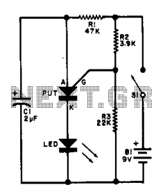
Led flasher IIV
This flasher circuit functions as a relaxation oscillator, with capacitor C1 discharging periodically through the LED when the Programmable Unijunction Transistor (PUT) is activated. The flashing rate is approximately 100 times per minute, based on the specified component values.
The flasher...
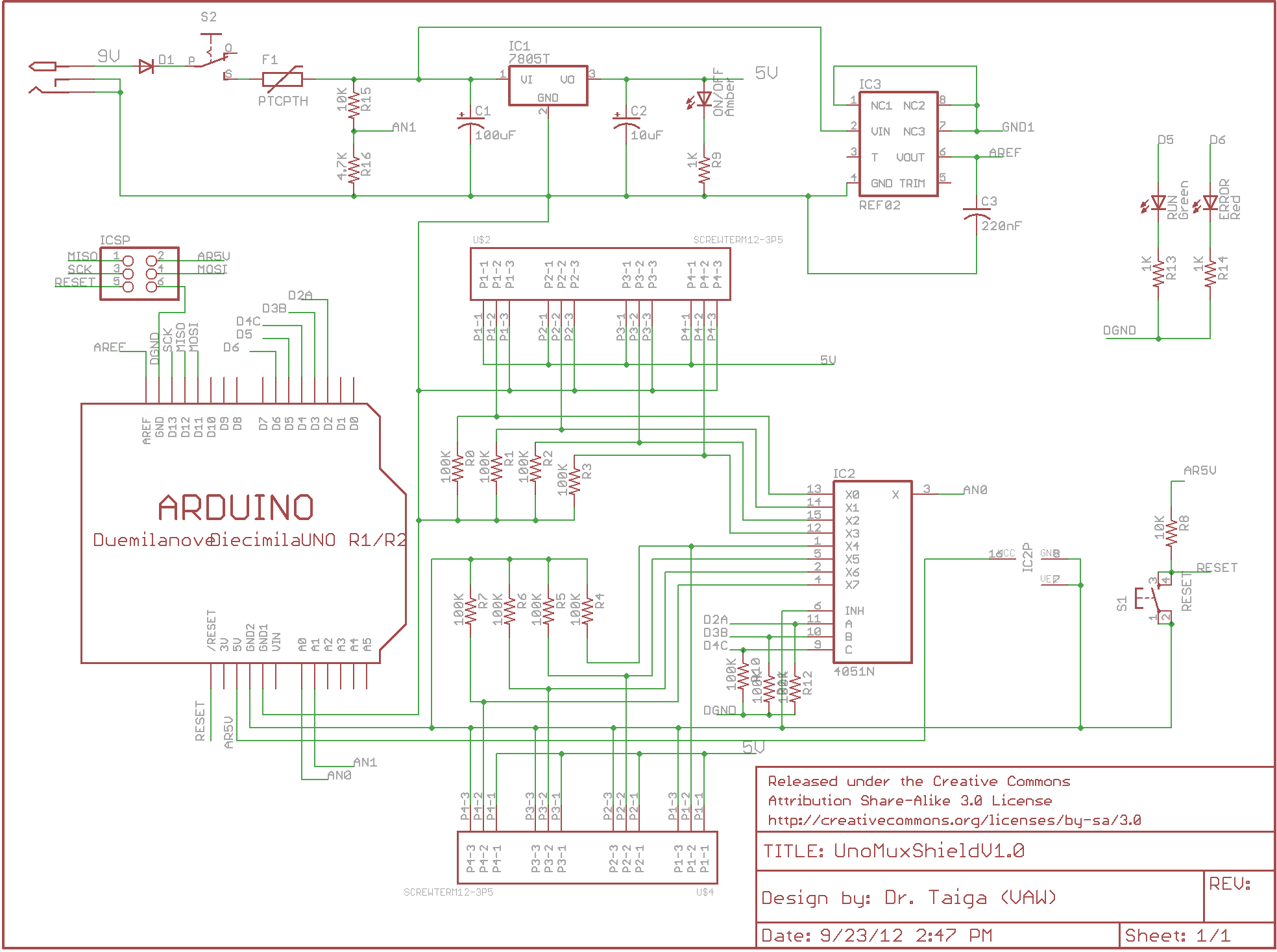
arduino multiplexer shield
There is enthusiasm for using Arduinos in science projects. However, it is important to address several shortcomings of the Arduino before it can be utilized for more serious applications. Specifically, the addition of robust screw terminals is necessary.
The Arduino platform...

Four flashing lights string circuit 2
The circuit utilizes a four-way slowly dimming LED driver integrated with iU shoe production and a Qis four flashing lights string controller. The C3484 manifold is specifically designed to operate Ji lights with four lights that flash and slowly fade....
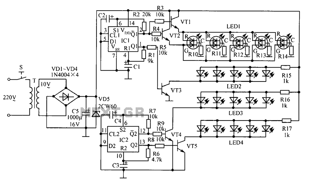
Bonsai electronic circuit
The electronic components designed by conventional electronic bonsai create a sparkling and brilliant atmosphere in the living room, enhancing the joys and pleasures of life. The selection of components includes IC1 to IC4, which consist of two pairs of D...
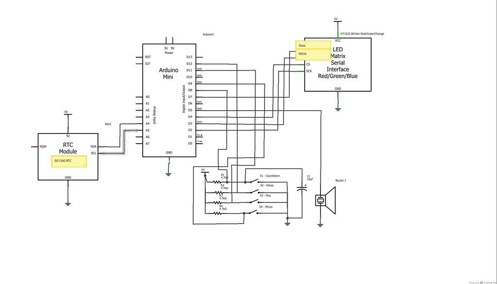
Colorful Countdown Clock for tight timeline management using Arduino
The device is designed to promote respectful time management during meetings, particularly useful in ship-room or SCRUM meetings. The following is a list of components required, including links for purchasing specific parts. It is advisable to check eBay or other...
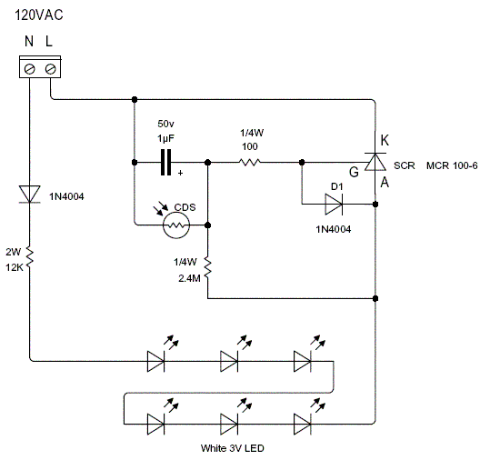
LED Night Light
This is a new circuit I just finished. I like the white LED lighting, it is softer and gives a better view without being overly bright for the eyes when you just wake up in the middle of the night....
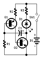
LED or Lamp Flasher
Flashing frequency can be varied by changing R1 value in the 1M - 4M7 range. This circuit is very efficient when driving a small 3.2V incandescent lamp. In this case omit the LED and R3, connecting the bulb across Q2...
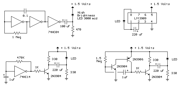
1.5 Volt LED Flashers circuit
The LED flasher circuits operate on a single 1.5-volt battery. The circuit on the upper right utilizes the popular LM3909 LED flasher IC and requires only a timing capacitor and an LED.
The LED flasher circuit using the LM3909 integrated circuit...