


Schematic of a Breadboard Arduino
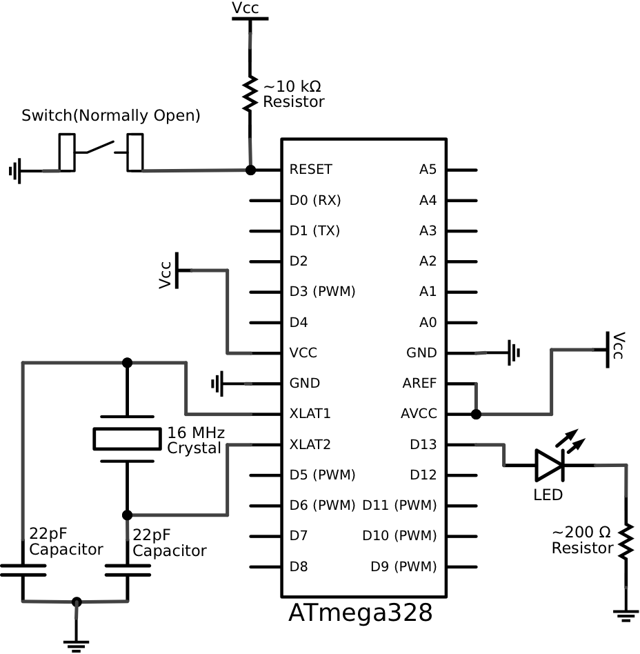
Description: This schematic represents a minimalistic circuit that includes only the essential components required for operating an ATmega328 microcontroller with the Arduino Uno bootloader. The design of the voltage regulation circuit is left to the user. Connections to AREF and AVCC are included, although they are only necessary if the analog-to-digital converter (ADC) of the chip will be utilized. The ADC and all analog pins can be disabled in projects to conserve power. The pull-up resistor connected to the RESET pin can be any value between 1 kOhm and 100 kOhm. The current-limiting resistor for the Arduino indication LED on pin D13 should be chosen based on the system voltage and the specifications of the LED.
The schematic focuses on the fundamental connections required for the ATmega328 microcontroller. It is designed to facilitate a straightforward implementation, ensuring that users can easily integrate it into their projects. The ATmega328 is a widely used microcontroller in the Arduino ecosystem, known for its versatility and ease of use.
In this schematic, the essential connections include power supply pins, ground, and the necessary programming interfaces. The microcontroller operates at a voltage typically ranging from 1.8V to 5.5V, with 5V being the standard for Arduino applications. The voltage regulation circuit, which the user must design, is crucial for maintaining a stable voltage supply to the microcontroller and its peripherals.
The AREF pin is used for providing an external reference voltage for the ADC. If the ADC functionality is not required, this pin can remain unconnected. The AVCC pin should be connected to the same voltage as the VCC pin to ensure proper operation of the ADC.
The RESET pin is essential for initializing the microcontroller. A pull-up resistor is recommended to ensure the pin remains high during normal operation, with a value between 1 kOhm and 100 kOhm being suitable. This resistor helps prevent accidental resets due to noise or interference.
The LED on pin D13 serves as a visual indicator of the microcontroller's operation. The current-limiting resistor for this LED must be calculated based on the forward voltage and current specifications of the LED, as well as the supply voltage. This ensures that the LED operates within its safe limits while providing adequate brightness.
Overall, this schematic serves as a foundation for various projects utilizing the ATmega328 microcontroller, allowing for customization and expansion based on specific project requirements.This schematic is for an extremely bare-bones circuit and includes only the needed components to operate a ATmega328 running the Arduino Uno bootloader. I leave it to you to design your voltage regulation circuit (see this post ). The connections to AREF and AVCC are only needed if you intend to use the chip`s ADC, but I included these connections anyway.
I usually turn the ADC and all of the analog pins off for my projects to save power (see this post ). The pull up resistor to the RESET pin can be any reasonable value between 1 and 100 kOhm. The value of the current limiting resistor connected to the Arduino indication LED on pin D13 should be selected to suit your system voltage and LED (see this post ).
The schematic focuses on the fundamental connections required for the ATmega328 microcontroller. It is designed to facilitate a straightforward implementation, ensuring that users can easily integrate it into their projects. The ATmega328 is a widely used microcontroller in the Arduino ecosystem, known for its versatility and ease of use.
In this schematic, the essential connections include power supply pins, ground, and the necessary programming interfaces. The microcontroller operates at a voltage typically ranging from 1.8V to 5.5V, with 5V being the standard for Arduino applications. The voltage regulation circuit, which the user must design, is crucial for maintaining a stable voltage supply to the microcontroller and its peripherals.
The AREF pin is used for providing an external reference voltage for the ADC. If the ADC functionality is not required, this pin can remain unconnected. The AVCC pin should be connected to the same voltage as the VCC pin to ensure proper operation of the ADC.
The RESET pin is essential for initializing the microcontroller. A pull-up resistor is recommended to ensure the pin remains high during normal operation, with a value between 1 kOhm and 100 kOhm being suitable. This resistor helps prevent accidental resets due to noise or interference.
The LED on pin D13 serves as a visual indicator of the microcontroller's operation. The current-limiting resistor for this LED must be calculated based on the forward voltage and current specifications of the LED, as well as the supply voltage. This ensures that the LED operates within its safe limits while providing adequate brightness.
Overall, this schematic serves as a foundation for various projects utilizing the ATmega328 microcontroller, allowing for customization and expansion based on specific project requirements.This schematic is for an extremely bare-bones circuit and includes only the needed components to operate a ATmega328 running the Arduino Uno bootloader. I leave it to you to design your voltage regulation circuit (see this post ). The connections to AREF and AVCC are only needed if you intend to use the chip`s ADC, but I included these connections anyway.
I usually turn the ADC and all of the analog pins off for my projects to save power (see this post ). The pull up resistor to the RESET pin can be any reasonable value between 1 and 100 kOhm. The value of the current limiting resistor connected to the Arduino indication LED on pin D13 should be selected to suit your system voltage and LED (see this post ).
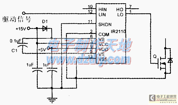
Design and making of the stabilized voltage supply of switch
Under the loading condition of the resistance, the output voltage (Uo) variable range is from 30V to 36V, with a maximum output current (Imax) of 2A. When the input voltage (U2) changes from 15V to 21V, the voltage regulation factor...
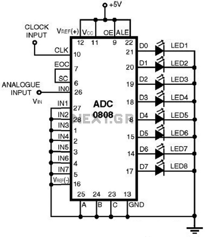
ADC0808 - Simple Analoque to Digital Converter
This is a straightforward analog-to-digital converter circuit utilizing an 8-bit analog-to-digital converter (ADC0808). Typically, an analog-to-digital converter (A/D Converter / ADC) necessitates interfacing with a microprocessor to convert analog signals.
The ADC0808 is a widely used 8-bit A/D converter that can...
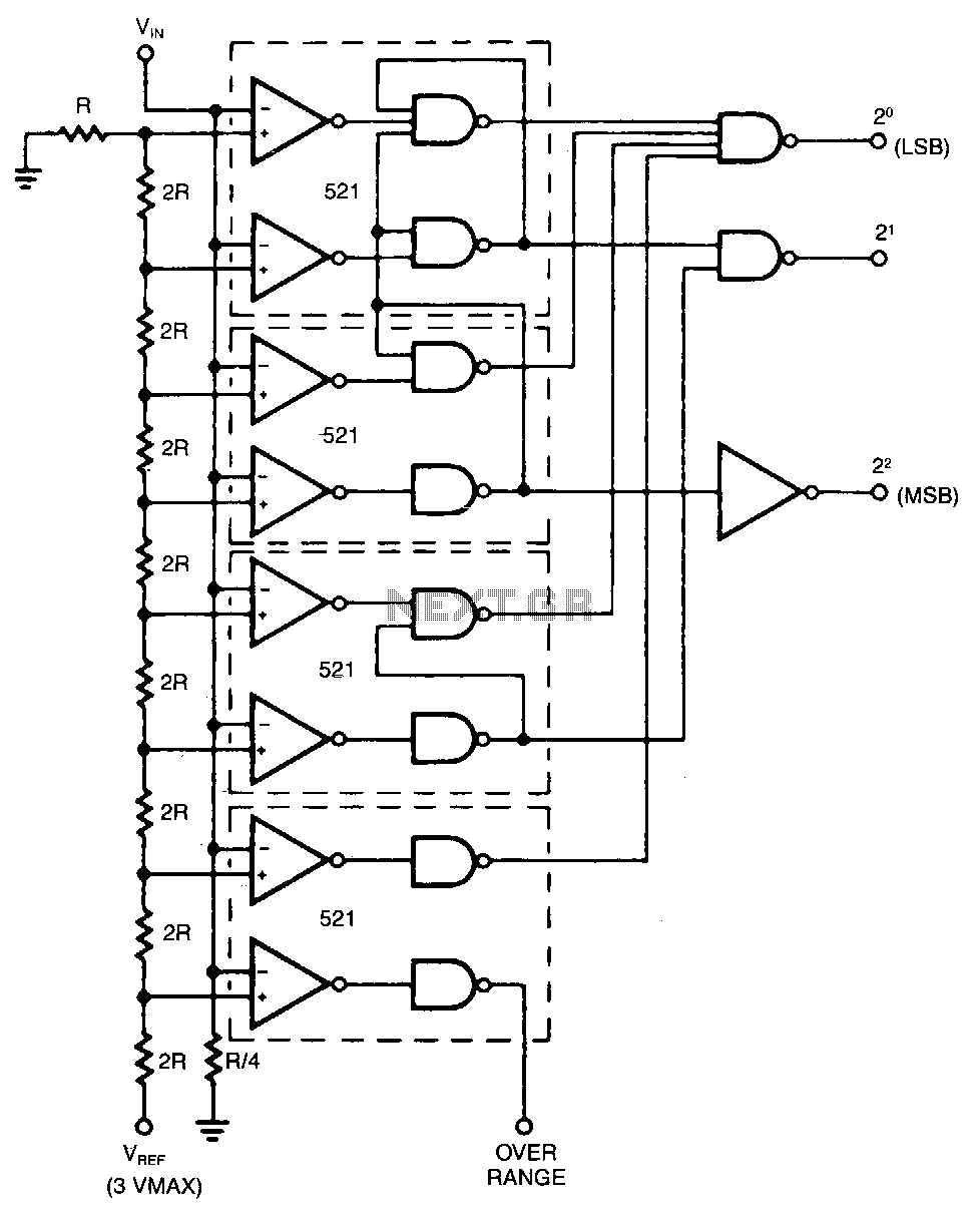
Adc
The conversion speed of this design is the sum of the delay through the comparator and the decoding gates. Reference voltages for each bit are developed from a precision resistor ladder network. Values of R and 2R are chosen so...
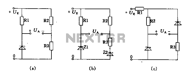
Bridge voltage regulator circuit diagram using the
The circuit depicted in Figures A, B, and C demonstrates a high voltage coefficient. When the regulator resistance \( r_z \) is held constant, the bridge configuration achieves an infinite voltage coefficient. In Figure A, the load circuit is connected...
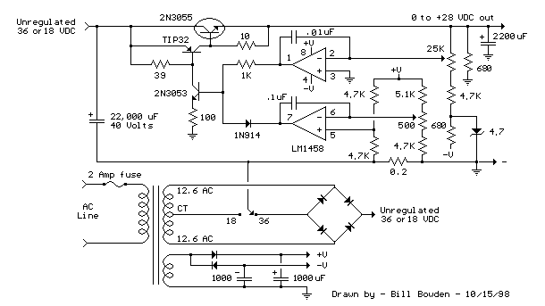
variable voltage and current power supply
An alternative method for utilizing operational amplifiers (op-amps) to regulate a power supply is illustrated below. The power transformer necessitates an additional winding to provide the op-amps with a bipolar voltage of +/- 8 volts. This negative voltage is also...
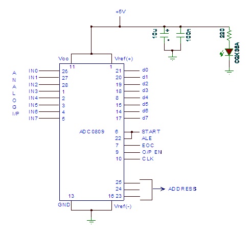
analog to digital converter module
Analog to digital converter modules are utilized in microcontroller-based projects where analog signals need to be transformed into digital signals for further processing in a microcontroller. The integrated chip employed for this purpose is the ADC 0809. This post briefly...
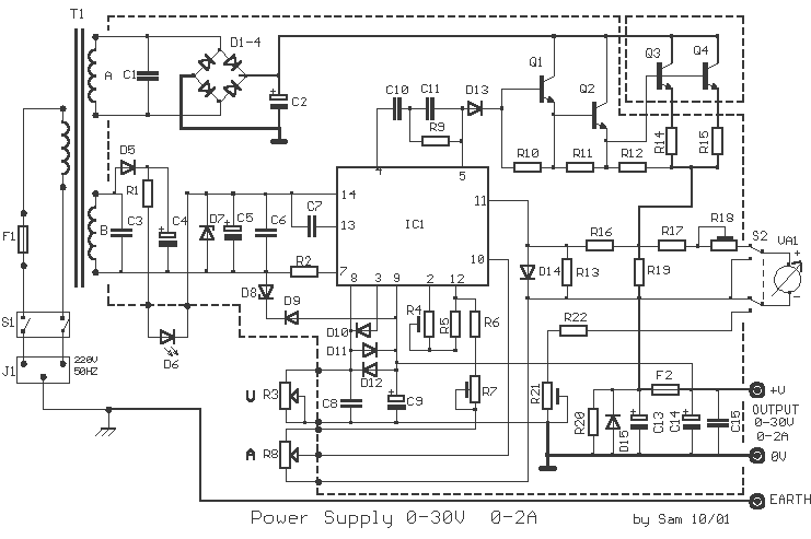
Power Supply 0-30V / 0-2A
The basic requirements for a laboratory power supply are to provide the necessary voltages and currents with low output resistance, low noise, minimal ripple, and good stabilization. These requirements are addressed within the circuit design. Many power supplies incorporate electronic...
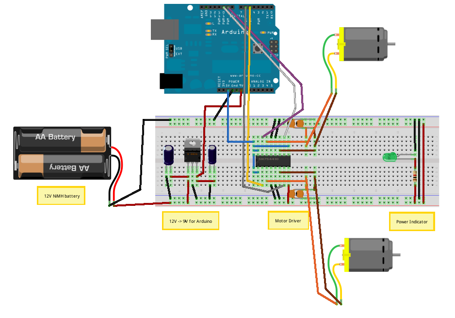
Voltage Regulators
Until Willow Garage was acquired, there was work as a Web Robotics Engineer. This title reflects a role as a full-stack engineer focused on real-time, distributed robot control. Notable projects include an XML-RPC server and client for Node.js, a deprecated...
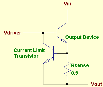
protected
A voltage regulator is designed to provide a fixed voltage to any load. This inherently means it must supply the necessary current through that load to satisfy Ohm's Law, I = V/R. As the resistance (R) approaches zero, such as...