


Traffic Lights Beginner Arduino Project
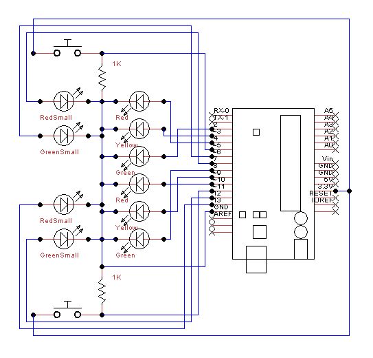
Description: Set up the lights on the breadboard to resemble a traffic light configuration. The red LED should be positioned at the top, followed by the yellow LED, and then the green LED. The small red and green LEDs will represent the pedestrian crossing signals, with the red LED placed on top and the green LED directly below it. Ensure that the buttons are installed with at least two pin holes of space available for connecting wires and resistors. A 1 kΩ resistor should be placed between one terminal of the button and the negative rail on the breadboard.
To create a functional traffic light circuit on a breadboard, the following components are required: three LEDs (red, yellow, green), two additional smaller LEDs (red and green for pedestrian signals), buttons, a 1 kΩ resistor, and jumper wires.
The main traffic light configuration consists of the three larger LEDs arranged vertically. The red LED is positioned at the topmost location on the breadboard, followed by the yellow LED in the middle, and the green LED at the bottom. Each LED should be connected to a suitable current-limiting resistor (typically around 220Ω to 330Ω) to prevent excessive current from damaging the LEDs. The anodes (longer leads) of the LEDs should be connected to the positive voltage supply, while the cathodes (shorter leads) are connected to the ground through the resistors.
The pedestrian crossing signals are represented by the smaller red and green LEDs. The red pedestrian signal should be placed directly above the green pedestrian signal. Similar to the main traffic lights, these LEDs also require current-limiting resistors connected in series.
The buttons serve as manual control mechanisms for the traffic lights and pedestrian signals. Each button should be connected with at least two pin holes of space on either side to accommodate the necessary wiring and resistors. The configuration involves connecting one terminal of each button to the positive voltage supply and the other terminal to the respective LED circuit. The 1 kΩ resistor should be placed between the button terminal connected to the LED circuit and the negative rail on the breadboard, ensuring that pressing the button completes the circuit and activates the corresponding LED.
Connections should be made using jumper wires to establish links between the LEDs, buttons, and the power supply. It is essential to verify the polarity of the LEDs and ensure that all connections are secure to facilitate proper operation of the traffic light system. This setup will allow for the demonstration of traffic light sequences and pedestrian signal activation in a compact and visually intuitive manner.Setup the lights on the breadboard like a traffic light. Red on top, then yellow, and then green. The small red and green are the pedestrian crossing signals. Again red on top and green just below. Put the buttons in so you have at least 2 pin holes space to add the wires and resistors. Place the 1kohm resistor between one side of the button and t he negative run on the breadboard.
To create a functional traffic light circuit on a breadboard, the following components are required: three LEDs (red, yellow, green), two additional smaller LEDs (red and green for pedestrian signals), buttons, a 1 kΩ resistor, and jumper wires.
The main traffic light configuration consists of the three larger LEDs arranged vertically. The red LED is positioned at the topmost location on the breadboard, followed by the yellow LED in the middle, and the green LED at the bottom. Each LED should be connected to a suitable current-limiting resistor (typically around 220Ω to 330Ω) to prevent excessive current from damaging the LEDs. The anodes (longer leads) of the LEDs should be connected to the positive voltage supply, while the cathodes (shorter leads) are connected to the ground through the resistors.
The pedestrian crossing signals are represented by the smaller red and green LEDs. The red pedestrian signal should be placed directly above the green pedestrian signal. Similar to the main traffic lights, these LEDs also require current-limiting resistors connected in series.
The buttons serve as manual control mechanisms for the traffic lights and pedestrian signals. Each button should be connected with at least two pin holes of space on either side to accommodate the necessary wiring and resistors. The configuration involves connecting one terminal of each button to the positive voltage supply and the other terminal to the respective LED circuit. The 1 kΩ resistor should be placed between the button terminal connected to the LED circuit and the negative rail on the breadboard, ensuring that pressing the button completes the circuit and activates the corresponding LED.
Connections should be made using jumper wires to establish links between the LEDs, buttons, and the power supply. It is essential to verify the polarity of the LEDs and ensure that all connections are secure to facilitate proper operation of the traffic light system. This setup will allow for the demonstration of traffic light sequences and pedestrian signal activation in a compact and visually intuitive manner.Setup the lights on the breadboard like a traffic light. Red on top, then yellow, and then green. The small red and green are the pedestrian crossing signals. Again red on top and green just below. Put the buttons in so you have at least 2 pin holes space to add the wires and resistors. Place the 1kohm resistor between one side of the button and t he negative run on the breadboard.
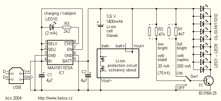
LED Flashlight circuit with MAX1811
White LEDs have a rated current at a voltage drop of about 3.3 to 3.4 V. It is ideal to be powered from the battery voltage which is slightly larger. Then there is the best energy used. In this I...
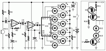
10 Dancing LEDs ElectronicCircuit Based On The LM358 IC
The following circuit illustrates a Dancing LEDs electronic circuit diagram. This circuit is based on the LM358 integrated circuit. Features: IC1A amplifies the signal.
The Dancing LEDs circuit utilizes the LM358 operational amplifier to create a visually appealing light display. The...
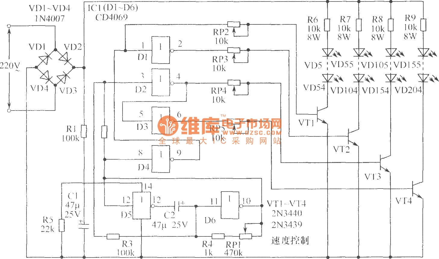
Christmas light circuit
The chart illustrates a Christmas lights circuit that employs a simple and cost-effective CD4069 CMOS hex inverter to control four separate circuits, each consisting of 50 light-emitting diodes (LEDs), totaling 200 LEDs. The circuit is powered directly by a 220V...
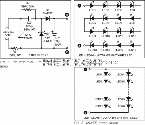
Ultra Bright LED Lamp
This ultra-bright white LED lamp operates on 230V AC with minimal power consumption. It is suitable for illuminating VU meters, SWR meters, and similar applications. Ultra-bright LEDs available in the market are priced between Rs 8 to 15. These LEDs...
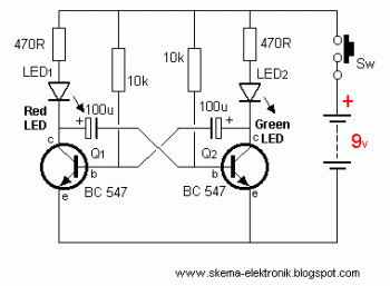
led lights using analog flip flop circuit diagram
This circuit is designed to drive a total of 42 LEDs, assuming a forward voltage of approximately 2.2V per LED and a forward current of around 21mA for adequate brightness. If the specifications of the LEDs differ significantly, modifications to...
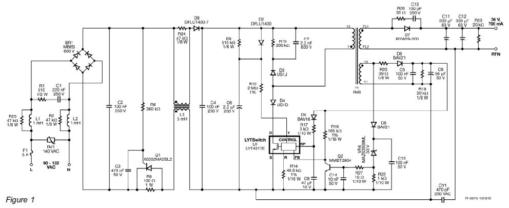
Driver and LED Companies must Work Together to Achieve High-Efficiency
The design of a PAR 38 LED spotlight focuses on delivering practical LED lighting systems that meet performance expectations by reducing power consumption, extending lifespan, and enhancing overall efficiency.
The PAR 38 LED spotlight is a widely used lighting solution in...
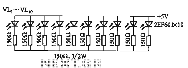
Flicker frequency of multiple sets of different light-emitting diode lights chain circuit
The circuit utilizes a 555 timer configured as a multivibrator, where the oscillation frequency is determined by resistors R1, R2, and capacitor C1. The frequency formula is given by fo = 1.443 / ((R1 + R2) * C1). The output...
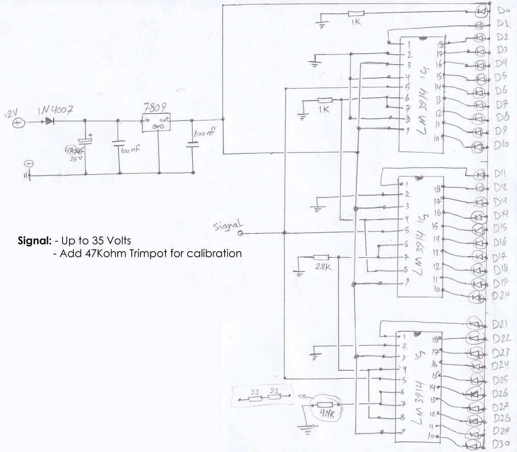
LED Speedometer circuit
The circuit schematics operate at 12 Volts, sourced from a car battery. The ground connection is tied to the car chassis, while the signal is received from a sensor connected to a stepper motor. The No. 5 pin of the...

Arduino UNO
The Arduino Uno schematic diagram is available for viewing. The Arduino Uno is a microcontroller board that utilizes the ATmega328 chip. It features 14 digital input/output pins, of which 6 can be used as PWM outputs, and 6 analog input...