


A simple passive logarithmic VU-meter
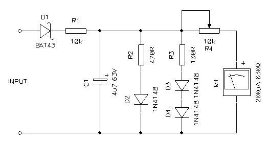
Description: A VU-meter is a common instrument typically found on audio Hi-Fi amplifiers, designed to display the instantaneous power delivered to the speakers. It is usually connected at the amplifier's output, in parallel with the speaker. The term "VU" stands for Volume Unit, with 0VU corresponding to +4dBm or 1.23RMS across a 600-ohm load. 0VU is often referred to as "0dB," and volume units are rarely utilized. In consumer electronics amplifiers, this standard is seldom met, and the meters generally indicate the amplifier's power without referencing any physical unit. The primary interest is in the power output to the speakers, rather than volume units. Thus, a meter providing a reading between zero and the maximum output power is generally sufficient. Audio volume is typically expressed on a logarithmic scale, reflecting the logarithmic nature of human auditory perception. Direct power readings in Watts may not effectively represent perceived volume. For instance, a few millivolts on an 8-ohm speaker are clearly audible. At low volume, speaker voltage may only reach a few hundred millivolts (milliwatts), while at medium volume, it rises to a few volts (around one Watt), and only at high volumes does the amplifier output its full power. Non-professional audio amplifiers often feature simple and ineffective VU-meters. For example, a circuit diagram found in an 80WRMS stereo set includes a diode rectifier (a voltage doubler consisting of C1, D1, and D2), a filter capacitor (C2), and a microammeter (M1). The full scale is adjustable via R1 to match the amplifier's maximum power output. However, this simple circuit results in a reading proportional to the peak output voltage, which is low and only increases significantly at high volumes, leading to meters that rarely move. Additionally, the use of a voltage doubler is questionable, as the speaker voltage is already sufficiently high, and the silicon diodes used have a forward voltage drop of about 0.6V, whereas germanium or Schottky diodes would have a lower drop. The doubler also has twice the forward voltage drop of a single diode, preventing small signals from being registered. Consequently, any signal below 1.2V peak will not move the meter, rendering this design ineffective. For meaningful readings, a logarithmic meter is necessary to measure both low and high power levels effectively. Professional or high-end amplifiers feature high-quality meters with logarithmic converters built from multiple op-amps and various components. However, a simple and passive logarithmic VU-meter can be constructed with minimal parts. Linear meters, like the previously described one, can also be converted. The fundamental concept involves utilizing the logarithmic characteristics of diodes to achieve a logarithmic response in an electromechanical microammeter. The circuit is straightforward and based on a standard 200µA microammeter, which is commonly used for such applications. The internal resistance is not critical and typically ranges between 500 ohms and 1k ohms. This circuit is designed for amplifiers capable of 80WRMS driving an 8-ohm load but can be easily adapted for different power levels or impedances. Similar power levels require no modifications, while significantly higher or lower levels necessitate adjustments to R4, and possibly R2 and R3. The AC signal across the speaker is first rectified by diode D1, which should be a germanium diode.
The VU-meter circuit design incorporates several essential components to ensure accurate power level readings. The primary elements include a rectifier, which converts the AC signal from the speaker into a DC signal, and a logarithmic scaling mechanism that adjusts the output to reflect perceived volume levels accurately. The rectifier, typically a germanium diode, is chosen for its low forward voltage drop, which allows for the detection of smaller signals that would otherwise be ignored by silicon diodes. Following rectification, a filter capacitor smooths the output to provide a stable DC voltage to the microammeter.
The microammeter, which serves as the display element, is calibrated to represent the logarithmic scale of the audio signal. To achieve this, the circuit employs a logarithmic response characteristic of the diodes, which allows for a more accurate representation of perceived loudness across a wide range of input levels. Resistors R1, R2, R3, and R4 play a crucial role in setting the scale and sensitivity of the meter. R1 adjusts the full-scale reading to match the amplifier's maximum output, while R2 and R3 may be altered to fine-tune the response for different power levels.
For applications requiring adaptability, the circuit can be modified by changing the values of R4, R2, and R3 to accommodate various amplifier outputs and speaker impedances. This flexibility ensures that the VU-meter can be effectively used in a variety of audio systems, providing reliable feedback on power output levels. Overall, this design offers a practical solution for creating a responsive and informative VU-meter that enhances the user experience in audio applications.A VU-meter is a very common instrument usually installed on audio Hi-Fi amplifiers and is used to show the instantaneous power provided to the speakers. It is usually connected at the output of the amplifier, in parallel with the speaker. The term "VU" stands for Volume Unit and should be defined with 0VU being equal to +4dBm, or 1. 23RMS across a 600 © load. 0VU is often referred to as "0dB" and volume units are very rarely used. In consumer electronics amplifiers this standard is rarely met and the meters only somehow display the power of the amplifier without referring to any physical unit. Anyway, the only thing one probably wants to know is how much power the amplifier is providing to the speakers and nobody really cares about volume units.
So a meter that gives a reading between zero and the maximum power output is fine enough (at least, for me). The audio volume is often expressed using a logarithmic scale because the feeling of sound intensity we get from our ears is also logarithmic and a direct power reading in Watts would not be very representative of the perceived volume.
For example, a few millivolts on an 8 © speaker are clearly audible. When listening at low volume, the voltage on the speakers is only a few hundreds millivolts (these are only milliwatts). When the volume is raised to a medium setting, the voltage on the speaker is around few volts (the power is around a Watt) and only when the volume is very high that all the watts of the amplifier are required.
Non-professional audio amplifiers often have simple (and useless) VU-meters. For example, the circuit diagram shown in the figure below was found in my stereo set (rated 80WRMS on 8 ©) and is composed by a diode rectifier (actually a voltage doubler composed by C1, D1 and D2), a filter capacitor (C2) and a microammeter (M1). The full scale is adjusted via R1 to match the maximum power output of the amplifier. But with this simple circuit, the reading is proportional to the peak output voltage which is always very low and goes up only when the volume is really too high.
So the amplifier has two nice meters that almost never move. Furthermore, the use of a voltage doubler is very surprising (and a bad idea), first because the voltage on the speakers is already high enough and there is no need to double, than because it`s composed by silicon diodes that have a forward voltage drop of about 0. 6V while germanium or Schottky diodes would drop much less, and finally because a doubler has twice the forward voltage drop of a single diode preventing small signals to go through.
In this configuration, any signal lower than 1. 2Vpeak has no chance of moving the meter. So this diagram has a big red cross: it`s a bad idea, don`t use it. In order to have meaningful readings, the meter should be logarithmic, allowing measures of low and high power levels without the problems mentioned above. Professional or high-end amplifiers have good meters with logarithmic converters built with many op-amps and lots of parts, but there is a way to build a simple and passive logarithmic VU-meter with only a few parts.
And useless linear meters like the one just described can easily be converted too. The basic idea is to use the logarithmic characteristic of diodes to obtain a logarithmic response of an electromechanical microammeter. The circuit is shown below and is really very simple. It`s based on a standard 200 A microammeter which is very very common for this kind of applications. Its internal resistance is not critical at all and is usually between 500 © and 1k ©. The circuit is intended to fit an amplifier capable of 80WRMS driving a 8 © load, but can easily be adapted to other power levels or impedances.
Similar power levels requires no modification, for much higher or lower levels, R4 must be modified and maybe also R2 and R3. First the AC signal across the speaker is rectified by diode D1. D1 should be a germa
The VU-meter circuit design incorporates several essential components to ensure accurate power level readings. The primary elements include a rectifier, which converts the AC signal from the speaker into a DC signal, and a logarithmic scaling mechanism that adjusts the output to reflect perceived volume levels accurately. The rectifier, typically a germanium diode, is chosen for its low forward voltage drop, which allows for the detection of smaller signals that would otherwise be ignored by silicon diodes. Following rectification, a filter capacitor smooths the output to provide a stable DC voltage to the microammeter.
The microammeter, which serves as the display element, is calibrated to represent the logarithmic scale of the audio signal. To achieve this, the circuit employs a logarithmic response characteristic of the diodes, which allows for a more accurate representation of perceived loudness across a wide range of input levels. Resistors R1, R2, R3, and R4 play a crucial role in setting the scale and sensitivity of the meter. R1 adjusts the full-scale reading to match the amplifier's maximum output, while R2 and R3 may be altered to fine-tune the response for different power levels.
For applications requiring adaptability, the circuit can be modified by changing the values of R4, R2, and R3 to accommodate various amplifier outputs and speaker impedances. This flexibility ensures that the VU-meter can be effectively used in a variety of audio systems, providing reliable feedback on power output levels. Overall, this design offers a practical solution for creating a responsive and informative VU-meter that enhances the user experience in audio applications.A VU-meter is a very common instrument usually installed on audio Hi-Fi amplifiers and is used to show the instantaneous power provided to the speakers. It is usually connected at the output of the amplifier, in parallel with the speaker. The term "VU" stands for Volume Unit and should be defined with 0VU being equal to +4dBm, or 1. 23RMS across a 600 © load. 0VU is often referred to as "0dB" and volume units are very rarely used. In consumer electronics amplifiers this standard is rarely met and the meters only somehow display the power of the amplifier without referring to any physical unit. Anyway, the only thing one probably wants to know is how much power the amplifier is providing to the speakers and nobody really cares about volume units.
So a meter that gives a reading between zero and the maximum power output is fine enough (at least, for me). The audio volume is often expressed using a logarithmic scale because the feeling of sound intensity we get from our ears is also logarithmic and a direct power reading in Watts would not be very representative of the perceived volume.
For example, a few millivolts on an 8 © speaker are clearly audible. When listening at low volume, the voltage on the speakers is only a few hundreds millivolts (these are only milliwatts). When the volume is raised to a medium setting, the voltage on the speaker is around few volts (the power is around a Watt) and only when the volume is very high that all the watts of the amplifier are required.
Non-professional audio amplifiers often have simple (and useless) VU-meters. For example, the circuit diagram shown in the figure below was found in my stereo set (rated 80WRMS on 8 ©) and is composed by a diode rectifier (actually a voltage doubler composed by C1, D1 and D2), a filter capacitor (C2) and a microammeter (M1). The full scale is adjusted via R1 to match the maximum power output of the amplifier. But with this simple circuit, the reading is proportional to the peak output voltage which is always very low and goes up only when the volume is really too high.
So the amplifier has two nice meters that almost never move. Furthermore, the use of a voltage doubler is very surprising (and a bad idea), first because the voltage on the speakers is already high enough and there is no need to double, than because it`s composed by silicon diodes that have a forward voltage drop of about 0. 6V while germanium or Schottky diodes would drop much less, and finally because a doubler has twice the forward voltage drop of a single diode preventing small signals to go through.
In this configuration, any signal lower than 1. 2Vpeak has no chance of moving the meter. So this diagram has a big red cross: it`s a bad idea, don`t use it. In order to have meaningful readings, the meter should be logarithmic, allowing measures of low and high power levels without the problems mentioned above. Professional or high-end amplifiers have good meters with logarithmic converters built with many op-amps and lots of parts, but there is a way to build a simple and passive logarithmic VU-meter with only a few parts.
And useless linear meters like the one just described can easily be converted too. The basic idea is to use the logarithmic characteristic of diodes to obtain a logarithmic response of an electromechanical microammeter. The circuit is shown below and is really very simple. It`s based on a standard 200 A microammeter which is very very common for this kind of applications. Its internal resistance is not critical at all and is usually between 500 © and 1k ©. The circuit is intended to fit an amplifier capable of 80WRMS driving a 8 © load, but can easily be adapted to other power levels or impedances.
Similar power levels requires no modification, for much higher or lower levels, R4 must be modified and maybe also R2 and R3. First the AC signal across the speaker is rectified by diode D1. D1 should be a germa
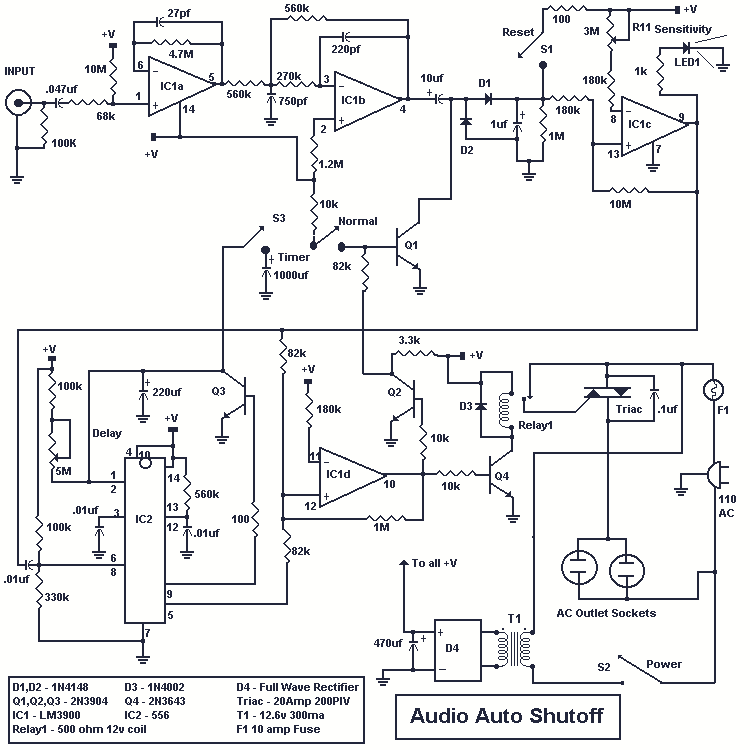
Automatic Audio Shutoff
The purpose of this circuit is to automatically turn off any device plugged into its power outlets after a certain period of time. Shutoff is activated by an absence of an audio signal or by a standard timer function. This...
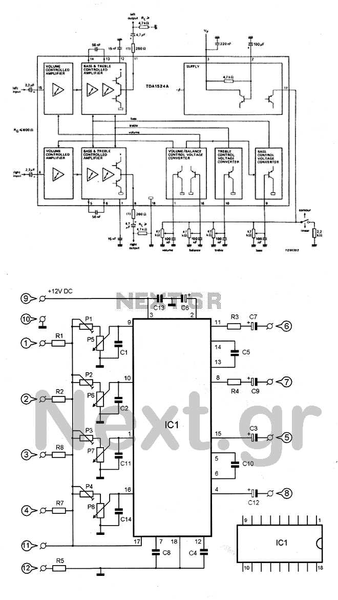
Hi-Fi stereo Preamplifier with tone controls
The circuit utilizes the TDA1524 chip, which is an integrated control unit for volume, bass, treble, and balance adjustments. Control is achieved through four potentiometers (P5-P8). The integrated circuit IC1 requires very few external components to operate. Potentiometers P1-P4 are...
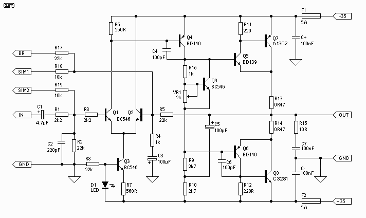
Updated 60-100W Hi-Fi Power Amplifier
The foundation of this amplifier is detailed in Project 03, which does not claim to be cutting-edge; the base design is over 20 years old. It is straightforward to assemble, utilizes readily available components, and is stable and dependable. The...
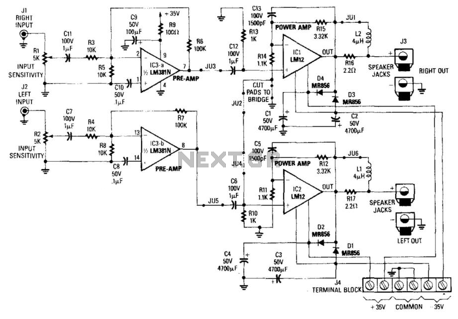
High-Power Car Audio Amplifier
Note for bridge configuration: 1. Install jumpers JU2 and JU4. 2. Remove J1. 3. Remove RIO. 4. Replace R13 with a jumper wire. 5. Replace R15 with a 4.53 kΩ, 1% resistor. 6. Replace R14 with a 13 kΩ, 1%...
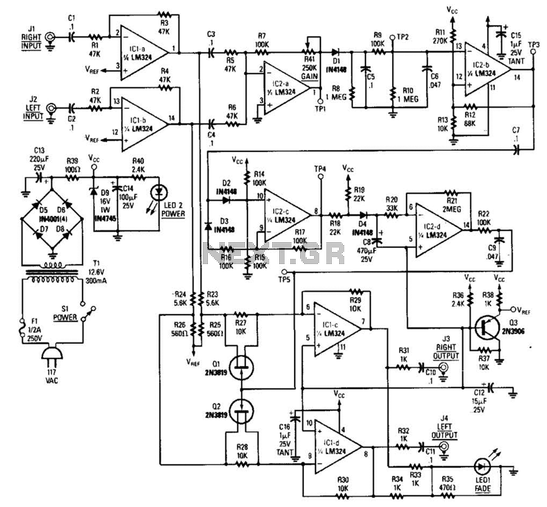
Radio Commercial Zapper Circuit
The LR inputs are summed, processed, and then drive a comparator. This comparator detects levels and generates transitions when audio inputs exceed or fall below predetermined thresholds. The frequency of these transitions, which correspond to rapid volume changes, is integrated...
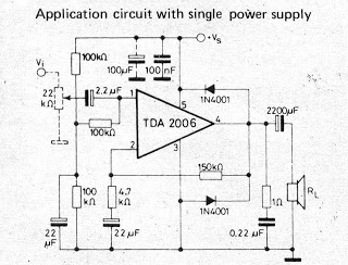
Small IC amplifiers for speakers
A small amplifier IC circuit has been compiled. This circuit is part of an older series and is categorized as a simple OTL (Output Transformer-Less) circuit.
The presented small amplifier IC circuit is designed for applications where compact size and simplicity...
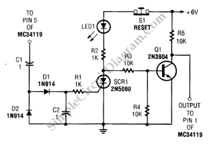
Ears and Speakers Protector
Occasionally, the output volume of an amplifier can be excessively high, leading to discomfort and potential damage to both the listener's ears and the loudspeaker. The circuit...
Amplifiers are crucial components in audio systems, responsible for boosting audio signals to drive...
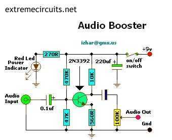
Mini Audio Booster Amplifier
This small amplifier circuit is ideal for boosting small audio units.
The small amplifier circuit is designed to enhance the audio signals from low-output devices, such as microphones or portable music players. It typically employs a transistor or an operational amplifier...
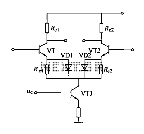
Emitter negative feedback differential amplifier gain control circuit
A controllable gain amplifier functions as an automatic gain control circuit within the execution unit. The primary methods for controlling the amplifier's gain involve two approaches: one is by adjusting certain parameters of the amplifier itself, such as emitter current,...